Home |
Community |
Forms |
Pictures |
Procedures |
- - - - - - -
- |
- - - - - - -
- |
| Mark's KLR650 Site Has Moved! *** This is old and outdated Information *** Please click the following link and change your bookmark to: ---------------------------------
|
WATER PUMP SEALS
REPLACEMENT |
| Thanks to MarkB for this procedure. This is his work entirely; I didn't have to do a thing but paste the text and images into the table, and add some simple font tweaks. |
Waterpump seal replacement: |
This is one of the easier "big jobs" on the KLR, even though you will need to remove the clutch cover (right side engine cover) to complete the job. You should have a Kawasaki KLR600 base manual handy before you start. It will help to see where the screws go, what the torque values are, and just for general reference. Take your time, make notes and draw a diagram of each piece that you remove, showing placement, and orientation; a simple diagram showing you how to properly reassemble the parts can be a real life saver. Pictures here should help in that regard. IMPORTANT UPDATE! Please be sure to read #18, Caveats and Pitfalls at the end of this procecedure. Thanks to -svt- for this information. |
Cooling System Overview: |
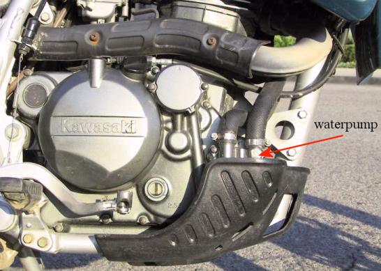
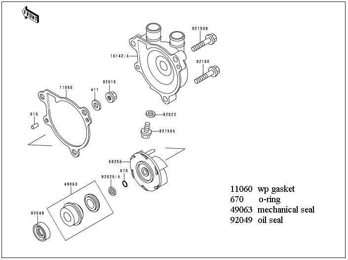
| The KLR650 uses a liquid cooled engine. The cooling system consists of a single radiator with electric fan, a thermostat mounted on the cylinder head, a waterpump to move the coolant through the system, and an overflow tank. The electric fan is controlled by a relay, which is triggered by a radiator mounted temperature pickup (referred to as the fan switch). Three coolant hoses provide the connections between the radiator, the cylinder head and the waterpump. The waterpump is driven off the forward balancer shaft (the two balancer shafts are chain driven off of the crankshaft). There are two seals for the waterpump. The first is an oil seal. This seal prevents engine oil from leaking out of the crankcase (and prevents contaminants from entering the crankcase). The second is a coolant seal (referred to as the mechanical seal), and this seal prevents the coolant from leaking out of the waterpump (and prevents contaminants from entering the coolant system). The impeller in the waterpump is mounted on an extension of the balancer shaft. The impeller must be removed to change the seals. For optimum results, plan on replacing the oil seal, the mechanical seal, the o-ring, and the waterpump cover gasket. Part numbers and suppliers are listed in the appendix. Replacement parts should cost $40 - $60 depending on the source. |
 |
 |
| |
Symptoms: |
There is a small weep hole located on the bottom
of the waterpump. If either of the seals on the water pump has
failed, engine coolant or engine oil may be leaking from this
hole. The usual indication of a failed waterpump seal is a few
drops of coolant coming from the weep hole, especially noticeable
just after riding the bike. The original coolant is green in color.
Note that some riders have reported riding an additional thousand
miles after the first leak before they replaced the seals. To
be more conservative, if it’s leaking, it’s time to
replace the seals. The middle of nowhere, or the side of the freeway
in rush-hour traffic are unfortunate places to find that the problem
has become too severe to continue riding. |
| |
Detailed How-to: |
WARNING: Make
sure engine is cool to the touch – hot coolant or hot engine
oil can cause severe burns. You will need a catch pan to collect
the coolant. Coolant capacity is 1.3 liters (about 1 & ½
quarts). Although you could reuse the coolant, replacing used
coolant with clean, fresh coolant will provide better cooling
and freeze protection. Protect your skin from engine oil and coolant
with nitrile gloves. |
| |
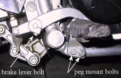
1. First, we need to get a
few things out of the way: Drain the engine oil into a suitable
container and dispose of properly. Next, remove the skid-plate,
then remove the clutch cable from it's mounting bracket on the
right side of the engine, and then from the clutch actuator lever.
Also, for clearance on the right side engine cover, you’ll
need to remove the right foot peg mount, and the rear brake lever.
The peg mount is held on by two 8mm bolts (12mm heads), and the
rear brake lever by a single 6mm bolt (with 10mm head). Note:
the rear brake lever is soft aluminum and over-tightening the
steel pinch bolt can strip the threads. If that happens you will
have to replace the lever, or perhaps install a Heli-Coil insert
to restore the damaged threads. |
 |
| |
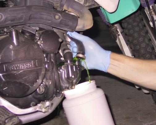
2. Remove and drain the two coolant hoses from the water pump, catching the coolant in a suitable container or disposable pan). The coolant system holds 1.3 liters.
|
 |
| |
3. Next, remove the water pump
cover (3 screws, (2) 6mm x 30mm, and (1) 6mm x 35mm, all with
8mm heads). Take a moment here to inspect the hoses for wear or
cracking and replace as needed. The stock hose set will cost about
$60 from the dealer, but a Goodyear #63936 heater hose can be
cut to fit all three pieces and costs about $25 Replacement hose
clamps are also available from your local auto parts store. |
 |
| |
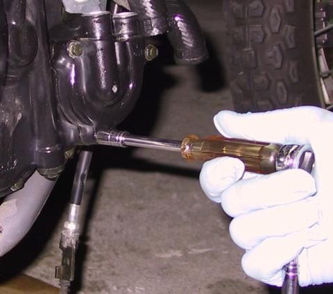
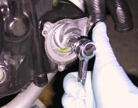
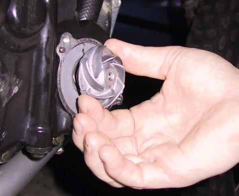
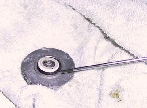
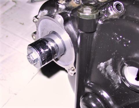
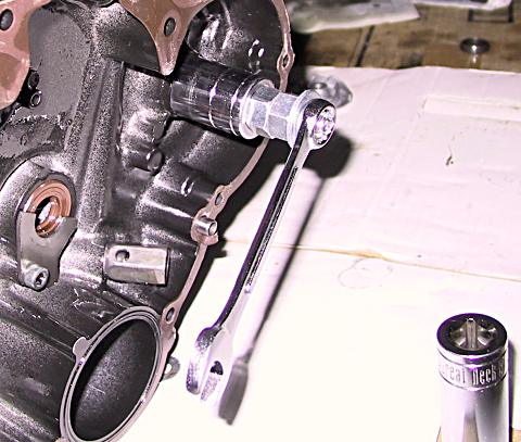
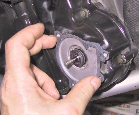
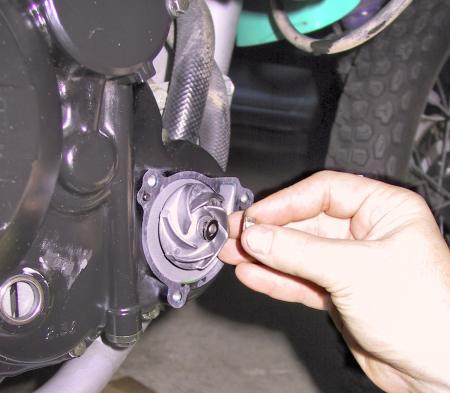
4. Remove the impeller - but
BE GENTLE! The waterpump
shaft is easy to break and expensive to fix. The impeller is held
on the shaft by a small nut (10mm head) and washer. After removing
the nut and washer, remove the impeller by rotating it slowly
counterclockwise while pulling it off. There is a thin washer
behind the impeller, remove this too and set all of the impeller
parts aside (the manual refers to this as a shim). |
 |
| |
 |
| |
 |
| |
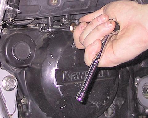
5. With the impeller off, it’s now time to remove the right side engine cover, (15 of those little case screws, again with one of them longer than the others.) It’s easy to over-torque these small engine screws so it’s best to use 1/4in drive socket sets and 6-point sockets. The screws are 6mm x 30mm with 8mm heads, with the one exception of the long screw installed just to the rear of the oil filter cover, which is 6mm x 80mm. With a few taps from a rubber mallet, the right side engine cover will slide off of the water pump shaft. If it won’t budge after several good whacks with the mallet, double check that you have removed all of the case screws. It should come off easy, not with brute force. |
 |
|
6. Seal removal: I made my own seal puller using a threaded bolt (3.5 in by 5/16 in), a few washers, and a couple of sockets (if you have or can borrow a seal puller, so much the better). First, put a small flat washer on the bolt, and then insert it from the inside of the case through the oil seal and mechanical seal. Alternative homemade seal puller by RC: 1)
I used the bolt referenced above with 5/16" flat cut washer.
The washers are Home Depot part number 32501. |
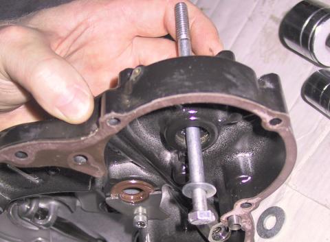 |
Then put a large socket (24mm or a 1 & 1/4
inch, 1/2inch drive socket) and a couple of washers on the outside
of the bolt where it sticks through the case (these are just spacers).
You need to use a socket large enough for the mechanical seal
to easily slide into. Put the nut on the end of the bolt and tighten
it up. |
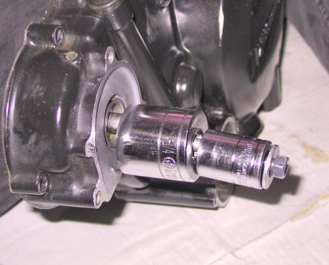 |
NOTE: Be careful
here, if the inside washer hangs up on the case, you can damage
the engine cover $$$. Make sure the washer you’re using
fits up against the seal, inside of the cut-out in the engine
cover – without catching on the case. With care, the seals
should easily come out in about a minute. A thin piece of gasket
material between the case and the large socket will protect the
smooth face of the waterpump, protecting it from scratching by
the rather crude seal puller. |
 |
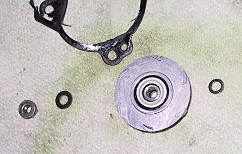
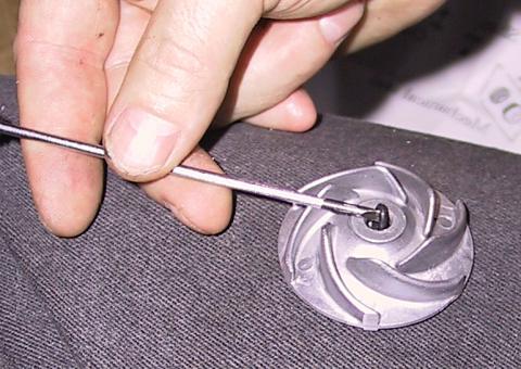
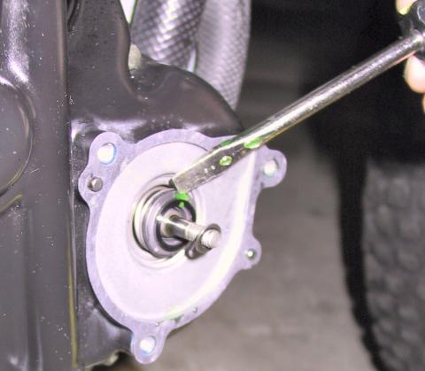
7. The other half of the mechanical seal is in the back of the impeller. It can be gently pried out with a small screwdriver (jewelers). Take care not to mar or scratch the impeller. Inside the impeller bore (where the shaft goes through) there is a small 6mm o-ring. Again, small screwdriver, pry gently, and be careful not to scratch the parts. Install the new o-ring into the slot inside the impeller bore, and place a few drops of oil inside the bore. Then fit the other half of the mechanical seal into the backside of the impeller (white ceramic thingy). |
 |
 |
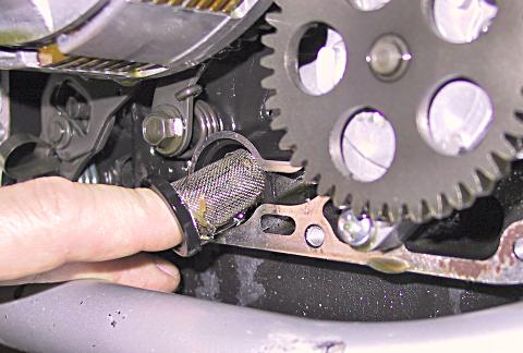
| 8. While you have the engine cover off, take a few minutes to clean out the oil pump strainer. It's a fragile looking little thimble shaped stainless steel screen with a rubber base. Pull it out and clean it carefully using a small brush and high flash point solvent, WD40 works well for this. Make sure the oil passageway behind the strainer is also clean and free from debris. If it's like mine, it will have caught metal shavings, clutch pieces, and rubber chunks from the balancer and cam chain guides. May also have globs of gasket compound from some sloppy mechanic or previous owner. Pull it out, clean it off and then check the oil galley behind it for any remaining debris. After cleaning it, re-install the oil screen. |
 |
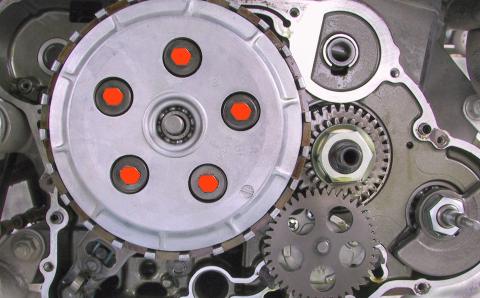
9. This is also a good time to inspect your clutch. While you have the engine cover off, do a careful visual inspection looking for wear or abuse. On high mileage bikes, you should consider replacing the clutch springs, as these springs will usually sag horribly with use (service limit is 33.1mm). Stock replacements are ~$2.50 ea from ronayers.com, so the entire set of five is less than $15. Order these with the waterpump seals and gaskets. The clutch plates and disks are behind the clutch cover plate, which is held on by five screws (6mm x 18mm, with 10mm heads). If you ride very aggressively, it’s recommended that you remove the clutch cover and inspect the steel plates and fiber friction plates. Service limit is 2.8mm for the friction plates. Check that the steel plates are not scorched (blueish tint). An aftermarket clutch kit could restore that snappy clutch response (EBC or Barnett are popular choices). |
 |
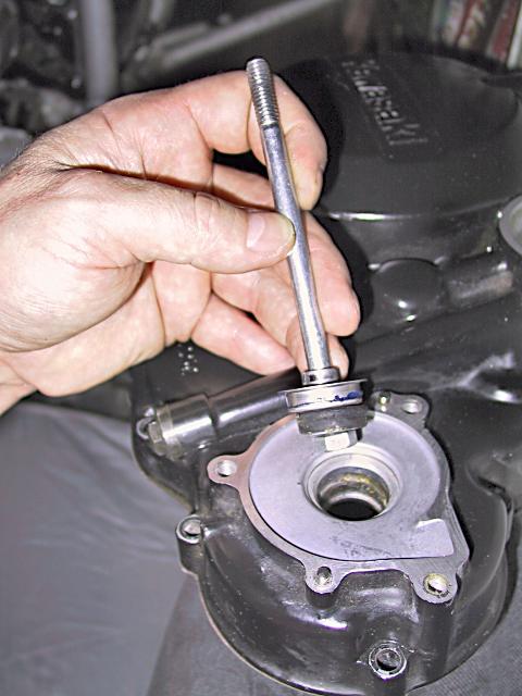
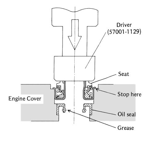
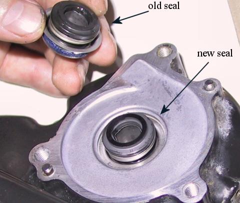
10. Now it’s time to install the new oil seal and the mechanical seal. The oil seal goes into the recess in the engine cover. With a few drops of fresh engine oil and a bit of thumb pressure, it should glide right into place. Check the seal from the internal side of the cover to be sure that it has come to rest against the shoulder on the inside of the engine cover, and that it sits squarely in the recess – not tilted to either side. Remember to install it with the smooth side out; check the diagram to be sure. The mechanical seal has a stainless steel base that supports the actual seal. This base has a fluted edge that rides against the shoulder in the engine cover. The next diagram shows a cut-away of the oil seal, mechanical seal, and engine case. The special driver tool forces the mechanical seal into the recess until the fluted edge is tight against the shoulder in the engine cover, and is used with a shop press. The same thing can be done with the puller -draw the seal base up tight against the shoulder. A 22mm, 12pt socket works perfectly for this - it is the same diameter as the seal base and still fits into the recess in the engine cover. Install a washer onto the puller bolt (step 6) and insert the bolt into the 22mm socket, then through the seals to the inside of the engine cover. Install a few larger sockets on the bolt to take up the excess length of the shaft, then install a flat washer and the nut. Finally, draw the nut down to pull the seal into place. Keep the bolt perpendicular to the engine case to be sure the seal does not get tilted at an angle where it will bind. Continue tightening until you feel the seal draw up tight against the shoulder. Give it a close visual inspection to ensure that the seal is mounted flush all around. |
 |
 |
 |
 |
11. Re-installing engine cover: Inspect the gasket surfaces on the engine cover on the engine case. Clean the mating surfaces on both the engine and engine cover. Do not scratch or gouge these surface, but be sure there are no lingering clumps of old gasket or sealer. Prep the mating surface on the engine side with a very thin coat of Hylomar gasket compound. Likewise, prep the engine cover mating with a thin coat of Hylomar. Carefully wipe away any excess gasket compound; a few minutes and some paper towels are cheap compared to the possible damage caused by loose globs of gasket compound that can clog oil passages and the oil pump intake screen. If you are careful, you may be able to re-use the original gasket, if not use the new one you purchased with the other supplies. Press the gasket into place on the engine, lining up the holes in the gasket with screw holes in the engine case. The tacky Hylomar should hold it in position. Before placing the engine cover onto the engine, lube the water pump oil seal with a few drops of clean engine oil or engine assembly grease. Place the cover screws into position and hand tighten all screws. Using a torque wrench, tighten the cover screws to the recommended torque 8.1n-m / 6 ft-lbs / 72in-lbs– repeat: inch pounds). Be careful not to over- torque the case screws as they will either snap off or strip out the case threads. Both are a real pain to deal with. |
12. Impeller and waterpump cover: Clean the mating surface for the waterpump cover, being careful not to scratch or gouge the surface. Apply a thin coat of Hylomar, and press the new cover gasket into place, the Hylomar should keep the gasket in position. Check that the impeller is ready to be installed; with the new o-ring installed inside its slot in the bore, and the white ceramic half of the new mechanical seal installed in the back recess of the impeller. Before installing the impeller, wet the mechanical seal with a few drops of engine coolant. This provides the initial lubrication between the two halves of the mechanical seal. Next, install the impeller: first the thin metal washer, then the impeller, then the 6mm flat washer, and finally the retaining nut. When pushing the impeller onto the shaft, rotate it slowly clockwise while pressing it on. This prevents the threaded shaft from tearing the o-ring in the impeller bore. Torque the retaining nut to 9.8n-m / 87in-lbs / 7.25ft-lbs. Clean the mating surface on the waterpump cover and then prep it with a thin coat of Hylomar. Wipe off any excess, then fit the cover into place over the waterpump. There are three screws to hold the waterpump cover on, with the longer one going in the front-most hole. Torque the screws to 8.1n-m / 6 ft-lbs / 72in-lbs. Slip the hose clamps back into place over
the hoses, and reconnect the hoses to the bibs on the waterpump.
Take care to connect the hose from the cylinder to the front-most
fitting, yes, it’s marked “CYL”. Tighten the
hose clamps. |
 |
 |
 |
13. Re-install the foot peg mount and torque to spec, you don't want that thing coming off at the wrong time. Coat each bolt with a few drops of blue thread locker to prevent it from backing out. Remove and clean the brake lever mounting
shaft. The shaft is short and can easily be removed by sliding
it off to the inside. There is a spring that provides return
tension to the brake lever, note which way it goes so it can
be re-installed correctly. Clean the shaft and the bushing in
the mounting bracket using WD40 and some lint free rags. Then
lube the shaft with grease and re-install it with the spring.
Finally, re-install the brake lever onto the mounting shaft,
and connect the spring actuator for the brake light. Test the
switch position to be sure that it still lights up the brake
light when the lever is pressed. Note: The brake lever is soft aluminum and the pinch bolt is steel, so take care that you don’t over-tighten the bolt and strip out the threads in the lever. |
14. Reinstall the clutch cable,
being careful to route the cable where it will not be melted by
the exhaust pipe. The bolt for the cable holder is difficult to
access, and although it is somewhate tedious, a 10mm open-end
wrench usually reaches the head. |
15. Refill the engine with
good quality motor oil, but do not change out the filter just
yet. It should take about 2.1 liters or 2.2 quarts of oil to refill
the crankcase. |
16. To rinse the cooling system,
fill it with distilled water, and run the engine for 10 min. Then
drain and repeat the process. Note:
be careful with the hot water. After two rinsing
cycles, refill the radiator with a 50/50 mixture of high quality
coolant and distilled water (be sure the coolant is designed for
aluminum engines and radiators). Use only distilled water to dilute
the coolant. Tap water or drinking water both have impurities
that interfere with the chemistry of the coolant, increasing the
risk of corrosion for the engine and radiator. |
17. Take the bike for a test
run of about 20 miles, and after returning to the garage check
for any oil or coolant leaks, and for any missing or loose fasteners.
Finally, do a regular oil change, replacing the oil, the oil filter and filter cover o-ring. The o-ring usually lasts for years and years, but if you have enough miles on the bike to do the waterpump, it's a good idea to also replace the old filter cover o-ring as well. The full oil change after the 20 mile run is to purge any contaminants that may have fallen into the crankcase when you were working on the thing. The contaminants should be either caught in the oil filter or suspended in the oil. A full oil change is 2.5 liters, or about 2 quarts and 20 ounces (US). |
18)
Caveats and Pitfalls A). The 6mm O-ring is inside the impeller bore - about halfway - it is not obvious. It sits in a small groove and you have to peel it out with a dental probe or other small tool. Some recommend that it be replaced every time you remove the impeller. To avoid damaging this O-ring, screw the impeller on clockwise - pushing the impeller onto the shaft will certainly cut and damage the O-ring. B).
Always install oil seal (92049) prior to installing the mechanical
seal (49063). The mechanical seal consists of three pieces and is listed as part - 49063. The first piece has blue waterproof sealer, a spring with rubber face and it fits into the case. It should be driven gently until the lip is seated flush into the case using an appropriately sized socket (after first installing the oil seal). The other two pieces of the mechanical seal fit in back of the impeller - namely the white ceramic disk and its mating rubber 'ring' into which is the holder for the ceramic ring. Remember if you remove the mechanical seal, you MUST replace both the oil seal and the mechanical seal set. Don't forget the shims - one on each side of the impeller. C). After assembly, it is best to test you work for leaks using distilled water. Fill the bike with fresh oil in the crankcase and distilled water in the radiator. Then check for leaks. If you have a leak using antifreeze it most likely will contaminated your fresh oil, whereas a little water in your fresh oil will evaporate after you fix the leak. Check the weep hole to ensure it stays dry when you start and run the bike to operating temperature. If all is well, wait for the bike to cool and drain the distilled water by removing the two hoses at the water pump and the drain screw and refill with 50-50 silicate-free antifreeze mixture. D). The side case gasket seems to be resilient to reuse, assuming it didn't get damaged during removal. Use some Yamabond or other good motorcycle sealer if you reuse the gasket. Of course you do this at your own peril - the gasket is around $13. |
See you on the
road… MarkB A9, A3, A2 project bike |
Appendix |
Parts & Materials: 92144-1559, Clutch spring (5 needed) 16099-004, Oil filter (5) quarts of high quality engine oil, Suppliers: Ron Ayers Motorsports Your local Kawasaki dealership, which can
be found from their website: Your local auto parts store can provide the Hylomar, nitrile gloves, quality engine oil, quality antifreeze-coolant. Distilled water is usually available from your grocery store. |