Home |
Community |
Forms |
Pictures |
Procedures |
- - - - - - -
- |
- - - - - - -
- |
| Mark's KLR650 Site Has Moved! *** This is old and outdated Information *** Please click the following link and change your bookmark to: ---------------------------------
|
OIL SCREEN CLEANING |
This Oil Screen Cleaning procedure is initially based on the Water Pump Seals procedure done by MarkB, and hosted on this website here. This procedure specifies only the steps needed to accomplish the screen cleaning. Using care, I did NOT need to replace either cover gasket. The seals aren't messed with when simply doing an oil screen cleaning, so will be fine. If the seals are leaking, the information on how to deal with that problem can be found in the water pump seals procedure. |
 |
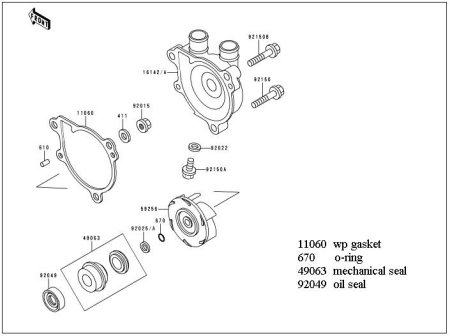 |
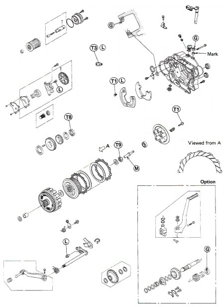
The
above scans show the engine right side and water pump area. This
is a very straightforward job, but it's probably a good idea to
have this parts breakdown available just in case... |
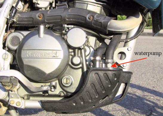 |
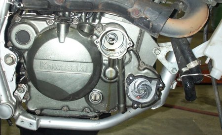
The
water pump housing is indicated above by the red arrow. You'll
need to remove whatever skid plate - stock or aftermarket - that
you have installed. |
1.
Start the bike, and let it run for a few minutes to warm the oil
and coolant. |
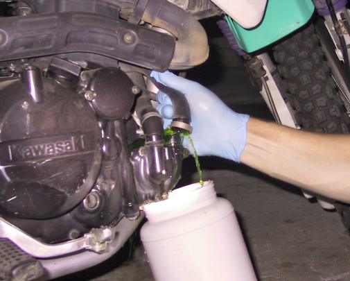
| 2.
Drain the engine oil, and remove the oil filter |
 |
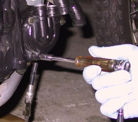
3. By now, the coolant should be at a manageable temperature. As shown above, drain the coolant by opening the radiator cap, and removing the small drain bolt at the bottom of the water pump housing. Loosen the two hose clamps at the water pump, and pull them off one at a time - keeping a container available to catch the old coolant. As long as you've drained most of the coolant anyway, I'd suggest that you remove one or both of the hoses at the coolant bottle and drain that, too. Inspect your hoses to see if they should be replaced. Stock Kawasaki hoses are expensive, but you can get a Goodyear #63936 heater hose, and cut it to the correct sizes. |
| |
Coolant
is very toxic, and should be handled and disposed of properly.
Animals, and possibly children, will find the taste appealing
- with disastrous results in either case. |
 |
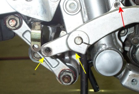 |
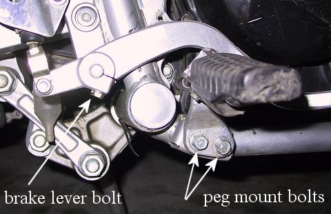
4. The pictures above show that the footpeg and brake lever need to be removed to gain the necessary clearance for the side cover to come off. - Remove the footpeg bolts - Remove the brake lever bolt and pin. The bolt is indicated in the top picture with a white arrow, and the pin by a yellow arrow in the bottom picture. - Remove the spring from the brake lever, indicated by the red arrow in the bottom picture. |
5.
Remove the clutch cable where it meets the actuator. I found that
all I had to do was use a boxend 10mm wrench to remove the bolt
holding the cable clamp, (just before the actuator), and I could
then slip the cable end out of the actuator without disturbing
the clutch cable adjustment. |
 |
6. As shown above, remove the water pump housing. The bolt on the upper right, at the outlet marked "To Cyl" is the longer of the 3 bolts used here. The housing should come off pretty easily. DON'T pry at it if you have trouble. Instead, try tapping around its perimeter as much as possible with a rubber mallet. Then just try gently rocking it off. |
 |
The
picture above shows that, except for the impeller, the cover is
about ready to come off. I tied the two heater hoses and clutch
cable back to be sure they stayed out of the way. Also, the brake
light spring is tucked safely out of the way. The coolant bottle
is hanging too because I wanted to have completely fresh coolant
in the system. I'm using Rotella 50/50 premix. |
 |
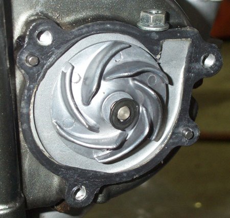 |
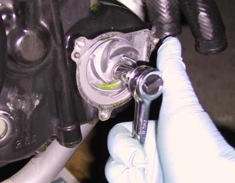
7. The two pictures above show that the impeller is next to be taken off. Brute force is not necessary here, and would be one of the very bad places to employ it. You don't want to break that shaft. The impeller bolt is installed using 9.8n-m / 87in-lbs / 7.25ft-lbs. That's not much, but IS enough to spin the shaft when trying to remove the nut. I used a very heavy duty screwdriver blade in the oil fill hole to catch a meaty "tab" of the clutch basket. I used this method to remove and install the bolt, and it worked quite well. On this side of the impeller, you'll have a washer and nut. Note that the gasket is in good shape. |
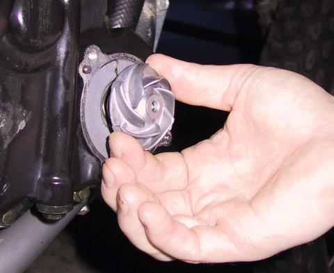 |
With
the nut and washer off, slowly rotate the impeller counterclockwise
as you gently pull back on it, as shown above. What you're doing
is working it off the rubber seal inside. |
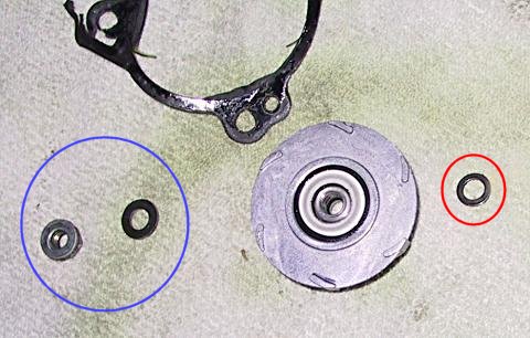 |
The
blue circle in the picture above is showing the nut and washer
found on the outside of the impeller. The red circle is showing
the small washer, or shim, that was behind the impeller. I thought
mine was not installed until I noticed that it had come off with
the impeller, and was stuck to it. |
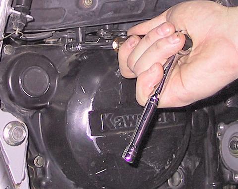 |
8. As shown above, it's now time to remove the side cover. There are 15 bolts, the single longer one is to the left, or rear, of the oil filter cover. Remove all the bolts and set them aside. Now, with all the bolts removed, tap around the cover with a rubber mallet. You're going to have to work at this a bit, it didn't come off as easily as I thought it would. I finally got some response when I put a finger into the oil fill hole, and rocked back and forth. Once the cover begins to come loose, try to work it evenly here and there to protect the gasket from damage. Once the cover is ready to come off, it will slide right over the impeller shaft. Don't mess with the seal there, it doesn't need any attention unless you're fixing a leak. And if you ARE, you need to reference the Water Pump Seals procedure. |
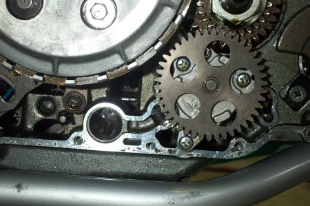 |
9.
Once the cover is off, you'll find the oil screen in the large
hole about in the center of the above picture, to the left of
the larger gear. Check there, and the other passages to be sure
that they're free of debris. I would expect that you will not
find anything in there if your oil screen is intact. |
 |
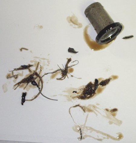 |
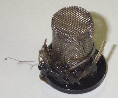
The
above two pictures show the junk that I found in mine. Oil was
certainly still flowing, but I was glad to get that stuff out
of there. What I found was rubber spaghetti,
and two small chunks of harder black rubber. |
That's about it. Clean the excess oil from the mating surfaces of the cover and engine. Clean the oil screen and put it back into place in the hole, as shown in previous pictures. The screen goes INTO the engine, with the rubber end closest to you. |
Installation
is pretty much the reverse of removal. The case screws can be
stripped and/or broken - a good torque wrench is our friend. I
like a little grease on the bolt ends, and use 8.1n-m
/ 6 ft-lbs / 72in-lbs
to install these bolts, and the water pump housing bolts. |
Once the case is reinstalled, you can reinstall the impeller, making sure that all washers are where they should be. Gently work the impeller over the shaft, as was done for the removal. NOTE: watch the position of the clutch actuator shaft as you reinstall the case. You may have to lift or slightly twist it back and forth in order for the cover to seat correctly. The swivelling head of the actuator should be pointing more or less straight toward the left side of the bike. Iif you find it's necessary - as I did - use a heavy screwdriver in the oil fill hole to keep the shaft from spinning, and install the impeller nut at 9.8n-m / 87in-lbs / 7.25ft-lbs. |
| Reinstall the clutch cable, brake lever and footpeg. Make sure to reconnect the brake light spring. There is a notch on the brake lever, and a dot on the brake lever shaft, (or vice-versa.) Line them up, and you're all set. |
Reinstall
the hoses, coolant and oil drain bolts, and refill with the appropriate
fluids. I choose Rotella 50/50 coolant, and Spectro Golden oil
. Your mileage may vary. |
Feel
free to email
me if you have any questions or problems. |