Home |
Community |
Forms |
Pictures |
Procedures |
- - - - - - -
- |
- - - - - - -
- |
Mark's KLR650 Site Has Moved! *** This is old and outdated Information *** Please click the following link and change your bookmark to: ---------------------------------
|
| HORN UPGRADE |
| Following is a before & after sound clip of the stock / Fiamm horns. This was done with a rather crappy handheld recorder, but should still give you a good idea of the vast improvement that two, higher decibel high/low tone horns will provide. |
| Click This Link For HORNS.WAV (About 458Kb) |
| Click This Link For HORNS.MP3 (About 233Kb) |
| Note on the Diagrams: Right-click them and save them to your drive; the text labels are clear if viewed locally. |
| PARTS: *I* used Fiamm trumpet style horns, F72112 - Low Note, 132db and A72002 - High Note, 125db. (I think a High Note alternative is E72102, but I'm not sure.) Buss Inline Fuse Holder, (30amp max), 20amp flat blade type fuse, Radio Shack 30amp, 12volt relay, Catalog #275-226, 14 gauge wire, and heat-shrink tubing. All connections were soldered where possible. |
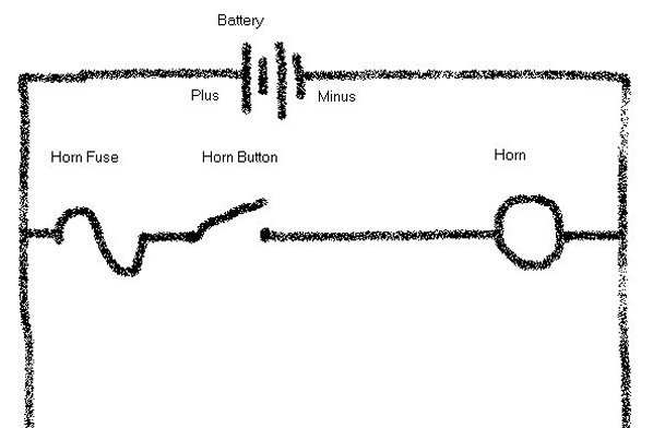 |
| Wiring Diagram by Bob: For the sake of clarity and comparison, the diagram above shows the way the wiring is set up for the stock horn. |
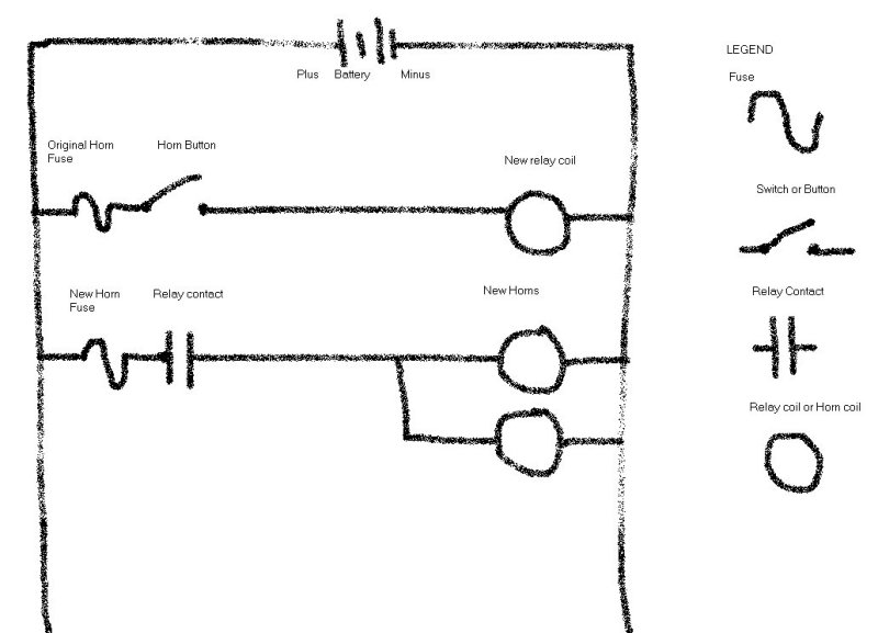 |
| Wiring Diagram by Bob: The diagram above shows the wiring for the new horns. |
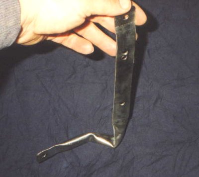 |
| You're limited in the way you mount the horns only by materials available and your imagination, the horns are not looking for ground through the bracket. The picture above shows a 1/4" piece of EMT bent in a vise, and hammered flat. Flexible strap, or whatever else you might want, can be used if it's secured so that nothing can come in contact with the coolant bottle. |
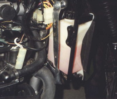 |
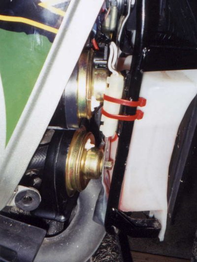
| The picture above shows the bracket on the bike. (The camera angle makes it look as though the bracket contacts the exhaust pipe, it doesn't.) NOTE: Mount the horns within the area of the coolant bottle, so that they are protected from the oncoming elements. Also, lower is better to avoid contact with the upper part of the gas tank. And last but not least, the trumpet horns are symetrical in that if arranged correctly they'll fit like puzzle pieces, one over the other. Mount them facing DOWN. |
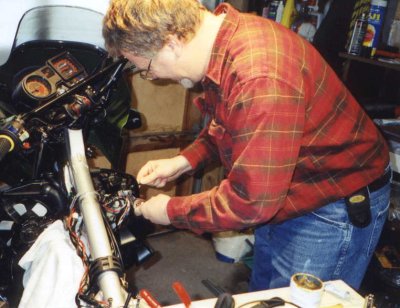 |
| When your friend is an electrician, you pass the tools while he does the wiring. Thanks again, Bob! The relay was mounted using the left wire holder/bolt, just above the white wiring connectors, and slightly to the right of the coolant bottle. We just removed the bolt and wire holder, added the relay and threaded the bolt back in. |
 |
| The picture above shows everything installed and ready to go, just to pop on the side/shroud cover. Next job is to put those extra inline flat fuse holders I bought to use, and replace the glass fuses here and under the saddle. |