Home |
Community |
Forms |
Pictures |
Procedures |
- - - - - - -
- |
- - - - - - -
- |
Mark's KLR650 Site Has Moved! *** This is old and outdated Information *** Please click the following link and change your bookmark to: ---------------------------------
|
| SAFETY SWITCH BYPASS |
| If you perform either or both of these bypasses, and bring the motorcycle to a mechanic, you should clearly note the fact that the safety switches have been bypassed, and the bike will start with the kickstand down, and the clutch out. |
| NOTE: This procedure was written so that the changes could easily be undone. From a legal standpoint, I think that you'd want to be able to restore this "safety" stuff if you were to sell the bike. If you're not concerned about that, you can save some work, and just solder the appropriate wires together... |
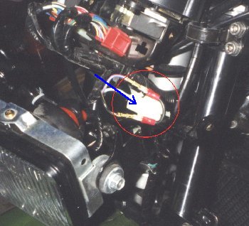 |
| CLUTCH
SAFETY SWITCH BYPASS: The picture above shows the wiring connector for the clutch safety switch. The connector and jumped wires are circled in red, the blue arrow points to the body of the connector. The wiring connector for the clutch safety switch is located behind a black protective box located under the instrument cluster behind the fairing. There are three wires wrapped in black tape running from the clutch switch to the connector, which fits in a mass connector plate to the left (shifter) side of all the others. The connector body is white. Unplug the connector from either side of the plate, and pull the two ends out into the open. There are two striped wires, and one solid wire that continue on to the main wiring harness. I used a very fine bladed screwdriver to reach up into the connectors and release the tabs that was holding the "spades" in place. Do this for the STRIPED WIRES, as these are the ones that need to be jumped for the circuit to work. I used tiny female spades, (available at the dealer), and made a jumper using 14 gauge wire, as shown in the picture above. Put a dab of di-electric grease (silicone) on everything. I left the solid wire in the connector body, and set it back up in the connector plate. I used heatshrink tubing on the jumpered striped wires, and wrapped them in black 3M electrical tape, securing them to the rest of the wires. Now, check to see that the neutral light works, and that the bike will start with the clutch lever out and the KLR in neutral. Button things up, and move on to the next step, if you wish. You can do one or both of these bypasses - but you don't have to do both for either one to work. There are circumstances that the sidestand bypass would be a good thing, but the clutch - IMHO - is the more "important" of the two because the safety switch WILL eventually fail. |
| |
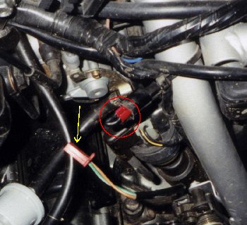 |
| SIDE STAND SAFETY SWITCH BYPASS: The picture above shows the switch connector in red, with the yellow arrow pointing to the female end that won't be needed any longer. Look for the long black plastic cover on the left side, just above the side stand. Remove this cover and follow the wires up to where they connect into the main harness, (on my 2001 KLR, the female end is red). The wires coming up to the female connector from the side stand are unused, (yellow arrow.) Fill the connector end with di-electric (silicone) grease, wrap it up with electrical tape, and secure it to something nearby. The wires in the connector at the main harness, circled in red, have to be jumpered to complete the circuit. I made another jumper with two female spades and 14 gauge wire. Make sure the female jumpers actually engage both male spades in the connector - it's easy to miss one in the tight space. Check to make sure the bike will start in neutral with the side stand down. Next, pull the clutch lever in, shift to 1st gear and slowly release the lever. If the engine DOESN'T die, you're all set to go. If it does die, you need to recheck your wiring. Button things up, and ride! |
Here's an alternative from John: Disassemble the switch itself, fabricate a "U" shaped piece of solid copper wire, and jump it across the contacts inside the switch. To make the switch work again, just unsolder the jumper. |