Home |
Community |
Forms |
Pictures |
Procedures |
- - - - - - -
- |
- - - - - - -
- |
Mark's KLR650 Site Has Moved! *** This is old and outdated Information *** Please click the following link and change your bookmark to: ---------------------------------
|
VALVE
CHECK & ADJUSTMENT PROCEDURE |
| The purpose of this page is to explain, in detail, how to check and adjust the valves on a KLR650. This is intended for people with modest mechanical skills, and/or those who have never undertaken a job such as this; I made an effort to be very specific about each step. |
| This is not a quick-start guide by any means, but rather is intended for people who are interested in doing their own work, and who prefer to work with a guide that spells out each step of the process. |
| Getting Started. |
| Make sure the engine area is cleaned of dirt, or anything that might find it's way into the engine once the valve cover is off. Set up the bike on a stable surface in an area where you'll be comfortable working for a while, an area that is as free from dust, bugs and whatever as possible. The engine must be cold before you can accurately check & adjust the clearances; generally, sitting overnight is best. |
| Tools. |
| You'll need an assortment of shims to cover any likely situation. Fred at www.arrowheadmotorsports.com carries a 16 shim set that is perfect for this, or you can get single shims if you prefer. You'll want a good ratchet and a metric socket set that includes 10,12 and 19mm sockets, and probably a couple different extensions. Feeler gauges from .002" to .012", tweezers and/or jewelers flat screwdriver and/or surgical "Kelly" clamp to get the shims out of the "cup", philips head and regular screwdrivers, non-drying silicone sealant such as Yamaha Quick Bond. |
| The Procedure. |
| 01. |
| Turn the fuel petcock to OFF. |
| 02 |
| Remove both side covers - 2 philips head screws each cover. |
| 03. |
| Remove the saddle hold-down bolts - 1 bolt on each side. There is a plastic "U" prong on the bottom front of the saddle that slips under a bracket, lift the saddle back up and pull the whole thing back to remove. |
| 04. |
| Remove the right radiator shroud - 2 bolts at radiator, 1 philips head screw at the top. |
| 05. |
| Remove the left radiator shroud - 2 philips head bolts backed by nuts at the shroud, 1 philips head screw at the top. |
| 06. |
| Remove the vent hose from the back of the gas tank. |
| 07. |
| There are 2 hoses to remove at the fuel valve/petcock: the gas hose, from which gas will come out, and a smaller vacuum hose up a little and behind it. |
| 08. |
| Remove the 2 mounting bolts holding the back of the gas tank to the frame. There are 2 sideways "U's" on the underside of the gas tank that hold it on 2 frame mounted studs. Lift the back of the tank slightly up and pull toward the back of the bike. A full tank of gas weighs about 35 pounds, be prepared to hold the weight. |
| 09. |
| Remove the 2 rubber "bumpers" on the gas tank mounting studs; this will improve clearance for the valve cover removal. |
| |
| |
| 10. |
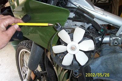
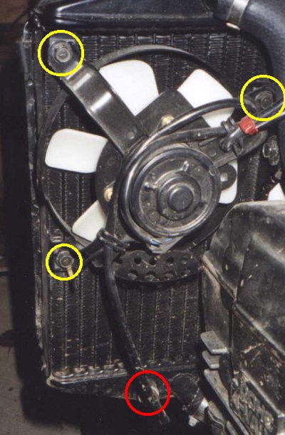
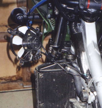
| The pictures above show the cooling fan mounted to the left side of the radiator using 3 bolts, and bungee corded out of the way. Remove these 3 bolts, and tie or bungee the fan out of the way. You can also unplug the gauge wire, circled in red, at the bottom of the radiator, beneath where the cooling fan was, to remove the entire assembly. |
 |
| Thanks to Dan for the picture above. Here's what he had to say: The cooling fan has one bolt that is a PITA to install. By notching the hole, I leave the bolt in and just slide it into place. |
| |
| 11. |
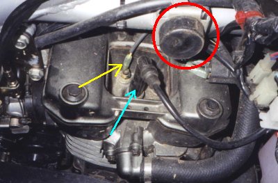
| Unplug the spark plug cap from the spark plug, but leave the spark plug in place. The spark plug cap and wire are shown above by the cyan arrow. The red circle shows one of the gas tank bumpers that I forgot to remove, but will remove before the cover comes off. |
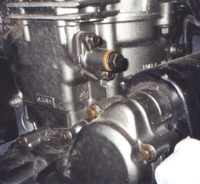
| 12. |
| Unplug the sensor wire. The sensor wire is shown above by the yellow arrow. |
 |
| 13. |
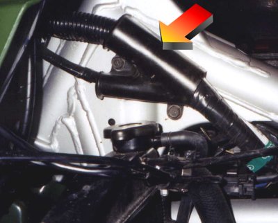
| The coil, shown above in the yellow circle, is mounted by one bolt on the right side of the engine, above and forward of the spark plug area. The spark plug wire is attached to one end of the coil, and 2 "spaded" wires are attached to the other. Remove the bolt and tuck everything out of the way. |
| |
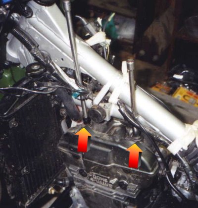
| 14. |
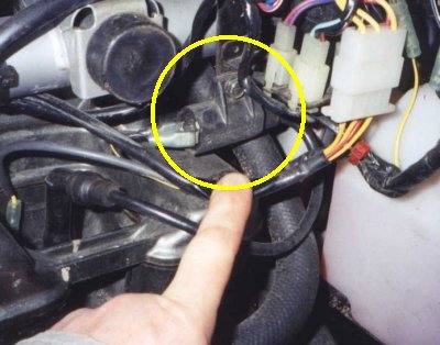
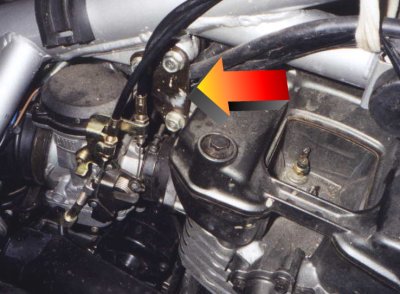
| To make the valve cover removal easier, remove the upper engine bracket, shown above by the large arrow. This is 2 Dorritos-shaped plates bolted to either side of the frame and engine using 2 bolts at the wider top, and one at the more narrow bottom. The bottom bolt has been treated with red, high strength Loctite, and screws into a small, heavy piece of flat stock on the left side. Remove the 3 bolts, 2 dorrito plates and small flat stock. This is not a necessary step, but it will make your life much easier if you do it. |
| |
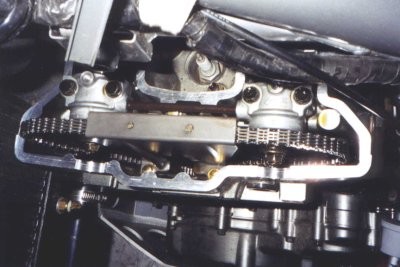
| 15. |
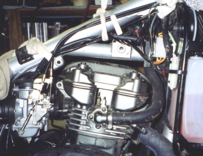
| The picture above shows that the path has been cleared for the valve cover removal. The radiator hose on the right side of the picture could be removed, but is very flexible and is easily pushed out of the way as the cover comes out. To make your life easier, move the wiring out from under the large frame tube that runs directly over the top of the engine. You may have to cut the ty-wraps to do it, and if you have replacements for them, or suitable tape, it's much easier to just snip them off. Like step 14, this is not a necessary step, but it will make your life much easier if you do it. NOTE: The cover is removed from the LEFT side, and comes out easier if you move it a little toward the front of the bike, (pushing into the soft radiator hose a bit), and then up and out. |
| |
| |
| 16. |
| Now for the valve cover. The right side valve cover bolts are right out in the open, but the left side ones are another story. The above UPPER picture shows the frame-mounted wire clamp that can be removed to allow the wiring harness to be moved away from the frame tube. The above LOWER picture shows sockets with extensions on the two left side valve cover bolts. If you use straight extensions such as these, they will not affect the accuracy of a torque wrench. DO NOT use a swivel, crows foot, or cheater pipe on the torque wrench handle as these will cause inaccurate torquing. I suspect it doesn't matter at all, but I would suggest removing the bolts in an "X" pattern; upper left, then lower right - upper right, then lower left. I would also suggest you use this pattern as you unscrew the bolts 1/4 turn each until loose. (I think all this helps keep the cover perfectly flat.) |
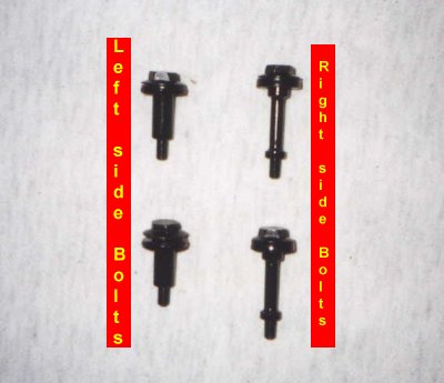 |
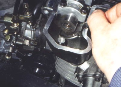
| 17. |
| (The picture above shows the valve cover bolts, and which side of the engine they go on.) With all the valve cover bolts out, the valve cover is ready to be popped off. Kawasaki uses, (and therefore, shouldn't we all use it!?), a non-permanent silicone sealant to ensure a leak-free assembly. Slight force will be required to remove the cover; I put my hands on either side of the engine just below the valve cover and use the force of my thumbs to exert an upward, alternating rocking force. Warning! The valve cover and engine top are precision machined surfaces, DO NOT pry the valve cover with anything - scratches or gouges in either surface would be an extraordinarily bad "mod!" |
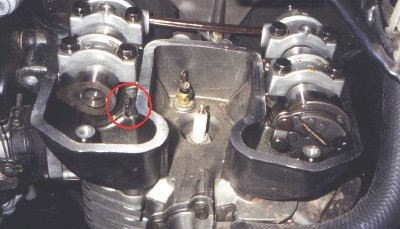 |
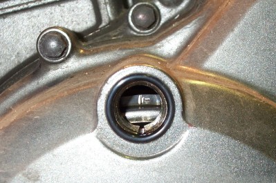
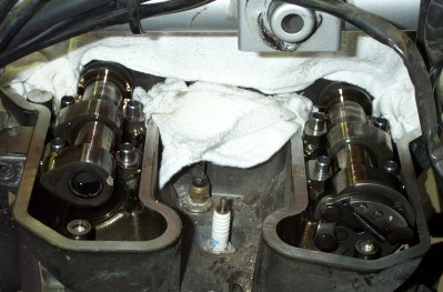
NOTE: The picture above shows the top of the engine with the valve cover off. You've got to work for it, but about in the center of the red circle is a slot in the "cup" that hold the shim. You can easily turn this "cup" until the slot is easily accessible - this is where you'll use a fine screwdriver, or tweezers to lift the shim out once the lobe has been lifted. You can also break the oil suction, and get the shim out more easily if you direct a short blast of air from an air nozzle at the cutout in the bucket. Be ready to prevent the shim from becoming a frisbee in case too much air is applied. |
Let's
establish some basics: |
| First. Left and Right is not a matter of perspective, or position; everything has only one left side and one right side. Sitting on the bike, facing forward, left is left and right is right. |
| Second. The intake is the back / carb side of the engine. The exhaust is the front / headlight side of the engine. Looking down at the top of the engine you'll see the 4 cams with shims underneath each one. They are: |
| Front Left = Left Exhaust <> Front Right = Right Exhaust <> Back Left = Left Intake <> Back Right = Right Intake |
 |
| 18. |
The picture above shows the Top Dead Center mark, TDC. On the lower left side of the engine, in the area just forward of the gear shift, are 2 round plastic slotted covers - a large one in the middle and a smaller one above it at the top. Both of these need to removed. A deep-well socket, or one with an extension, is used to turn the "nut" in the center hole counter-clockwise. Warning! Do not try to turn clockwise. If you miss the timing mark, even by a hair, go around again. You'll be watching for two things here; stroke and TDC mark. While turning the socket counter-clockwise, watch the intake cams and their valves. The cam will come around (counter-clockwise), and the more narrow tip of the cam will push the valve open, and then release the valve and allow it to close. You're getting close. As you slowly continue to turn, the cam tip will begin to release the valve and allow it to open. Now, look into the smaller upper hole that you removed the plastic cap from. You're looking for the 3rd of three marks, and they aren't far apart. First you see I, and then F, and finally the one you want, T. The leg of the T should be perfectly lined up with the notch cut in the bottom of the hole. Top Dead Center!! Note: At this point the marks on the camshaft sprockets point forward, and line up with the surface of the cylinder head. |
| At this point, save yourself some work and just check the clearances to see where you are, it's entirely possible that everything will be alright and you won't have to do a thing. It's very important that you keep careful track of all the measurements, before and after. I designed a form that has proven to be quite useful, and is available from the "Forms" page of this website, or just click HERE. The specification for the valve clearances is as follows: |
| Intake: 0.10mm – 0.20mm (0.004in – 0.008in) <> Exhaust: 0.15mm – 0.25mm (0.006in – 0.010in) |
| I feel there are too few riding days to waste tinkering with a bike. With that thought in mind, and with the knowledge that the valve clearances will close up over time, I suggest setting the valve clearances close to the top of spec and evening them out as much as possible. You've already got everything stripped down for the job, why not just do it and not have to think about it for another few thousand miles!? |
 |
| 19. |
| Checking the valve clearances is pretty easy. Use good quality, brand-name feeler gauges. They offer feeler gauges in the range that we need in a few different forms; regular size flat, small size flat, and regular size with a bend near the end; get whatever works best for you. (I like the ones with the bend at the end.) Start with a feeler gauge about in the middle of the spec for the cam clearance you're checking, and use larger or smaller ones until you get that "just right" fit. Be absolutely sure to correctly record each of the four clearances; again, the chart HERE is perfect for this. If things are OK the way they are, just button it all back up - if not, continue on... |
 |
| Warning! The Abyss, (shown above.) This is a part of the procedure where you can't be careful enough. A wrong move here that allows a cap locator or screw to fall down into the engine has made men go crazy, women faint, and children cry. (Undocumented information.) Those cap locators can fall out immediately as you lift up the caps, or trick you and not fall out for a couple seconds. Save yourself all kinds of heartache, and stuff clean, lint-free towels down in and around that left side of the engine, and don't remove them until the caps are secured back in place. |
 |
| 20. |
The Cam Chain tensioner bolt is shown above. Ok, the abyss is no longer an abyss, you're at TDC, have all 4 clearances correctly recorded, and are ready to proceed. On the upper left back side of the engine you'll find the cam chain tensioner - a larger center bolt head, (12mm), in a neck secured at the base to the engine by two smaller bolts, (10mm.) Remove only the 12mm center bolt, which is holding in a long, compressed spring. Be careful, as you remove the bolt, that the spring doesn't go shooting out and get lost. The reason the spring is removed from the tensioner before the cam(s) are disturbed is so it cannot get tighter either during the procedure. Nothing you are doing during the valve adjustment would cause a need for the tensioner to be tighter or looser than when you started unless the cams were disturbed before the tensioner was disabled by removing the spring. |
| 21. |
| On to the cam caps. The two right side caps, Intake & Exhaust, are separate and will easily come off individually. The two left side caps are connected by an oil feed pipe and must be lifted up evenly, equally and together, keeping the pipe in place between them. (I put the caps in the appropriate box on the FORM I made so as to not goof up when re-installing them. They must go into their correct places. The caps are marked, also.) |
| 22. |
| The cam chain tensioner bolt & spring are out, and the cam caps are off - 8 cap "tubes" are accounted for, right?! The cam chain is still attached on the left side, so don't go nuts and try lifting the shafts up 1 foot, but you can now lift the right ends of the cam shafts to gain easy access to the shims. The shims sit in a "cup," and this cup can be spun around until you find the notch where you'll use your tweezers, or whatever you choose, to get the shims out. Oil under the shims can create a slight "vacuum," so a slight amount of effort will be required to get the shims out. (My preference is to use a very thin jewelers screwdriver to pop up the shim, and a kelly clamp to grab and pull it out.) NOTE: As with the clearances, keep very close track of what size shim was at which valve - this is very important. I do one at a time, write each shim size on the form, and then place that shim in the appropriate box on the form. |
All this is written assuming a full, 4 valve clearance check. Note that the shims you removed were placed with the size numbers facing down, this is so the cam doesn't wear them off. Be sure to re-install the new shims number side down. If the size numbers ARE worn off, all is not lost. Obviously, if you have a micrometer or digital calipers that would be the easiest way to check the shim size. If you don't have either of these measuring devices: - place the shim on a perfectly flat surface such as glass. - lay a shim of known size tightly next to it, edge-to-edge. (from your spares or another bucket) - slide a finger nail across the surfaces from one shim to the other. Do this in both directions. A size difference will show up when the fingernail catches on a shim edge. If it doesn't, then you're probably good to go. - You'll want to scribe the center of an unmarked shim to avoid this trouble the next time. Do it now based on the assumption that you've gotten the size right, or install the shim and measure the clearance. NOTE: A worn shim can be reused by flipping it over, and scribing the size in the center of that surface. Scribing is done in the center of the shim to avoid having a burr from the scribing cause the shim to sit higher in the bucket. The center of the shim typically doesn't contact the bucket. |
You can do the math yourself, or save a lot of hassle and get a great program called ShimCalc from Pat at IronJungle. The website is at: http://www.ironjungle.com/ (ShimCalc Screen Shot) You will need three bits of information no matter how the figuring is done - Initial Measured Clearance / Stock Shim Used / Desired Clearance. Using ShimCalc, you just plug in these numbers for each valve and the software does the rest. (Stock Shim Used means the shim that was in there when you used the feeler gauge a few steps back to get the clearances.) |
I bought the 16 shim set from Fred Hink at www.arrowheadmotorsports.com to get started, and just replace the ones I've used so that I never have to fool around when I need a shim. I use this shim storage box to keep my spare shims rust-free, and oiled for use. |
| When you're all done with the job, I recommend you save the form with all the information you've recorded for future reference. Also, the shims you've taken out can be reused, generally. |
| 23.
|
According to what ShimCalc, or your math has indicated, put in the new shims - shown in the picture above. With the cam caps removed, you can lift the right end of the shaft to make room for the shim to come out. Make sure the shims are clean of protective coatings, dirt, or whatever. I like a light coat of fresh oil, (which comes from removing them from the muffin tin), to get them "started." Make sure the shims are completely seated in the cup when you install the new ones. You can also break the oil suction, and get the shim out more easily if you direct a short blast of air from an air nozzle at the cutout in the bucket. Be ready to prevent the shim from becoming a frisbee in case too much air is applied. |
NOTE:
It's a good idea at this point to pour some fresh, clean oil onto
the cam bearing surfaces, and the whole area in general - along
the shafts and such. |
 |
| 24. |
| Making sure the abyss rags are still doing their job, install the 8 cam cap locators, if necessary. |
| 25. |
| Put all the cam caps back in place, taking care to not disturb the pipe between the left side caps, and turn the bolts down finger tight. Make especially sure that on the left side you've correctly placed the caps so that they fit correctly over the ridge of the shaft on the chain sprocket side. Getting these two "connected" caps in place can be a little troublesome, don't force them! |
| 26. |
| Tighten the cam caps in the following order: (1) Left Exhaust - front bolt and then rear. (2) Right Exhaust - front bolt and then rear. (3) Left Intake - front bolt and then rear. (4) Right Intake - front bolt and then rear. The torque spec is: 12N-m / 1.2kg-m / 104in-lbs => NOTE: That's 104 INCH pounds. |
| 27. |
| You can safely remove the rags now. |
| 28. |
| Re-install the cam chain tensioner spring and bolt into the plunger body. Try to keep the spring as straight and even in the hole as possible. You'll hear the teeth ratcheting out as the spring is compressed into the hole by the bolt. |
| 29. |
| Now you're all set, with almost everything re-assembled, except for the valve cover. It would be a good idea to give it at least 2 or 3 full spins and re-check clearances to make sure all is as it should be. Remember, counter-clockwise only, and watch the stroke as in 18 to be sure you're correctly at TDC. |
| You should be all set, but if something somehow went wrong, you'll need to restart at step 20. Remember the abyss! |
| 30. |
Clean the top of the engine and the bottom of the valve cover of any silicone that may be on them. Use your fingernail to do this, not a scraper or any other tool - it's important to not damage the machined surfaces. Alternatively, you can use a plastic scraper of the type that fits into a razor scraper holder. Also, you can form pieces of plexiglass to do the job. If you don't have scrap plexiglass, check with a glass shop to see if they have any in their trash bin. Be sure to clean the plexiglass of any shavings or bits left hanging on. |
 |
| 31. |
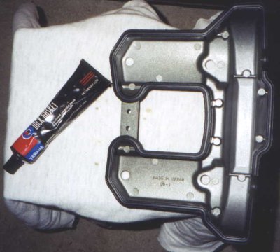
Use a small amount of non-drying silicone all around the rubber gasket surface of the valve cover. Be sure to wipe off any excess from the inside and outside edges of the cover. Again, you want very little here, just enough to lightly coat the surface and create a seal. I apply a small line of the silicone all the way around the gasket, then place my index finger on the top of the gasket, my thumb on one side of the gasket and my forefinger on the other side. I then just run around and around the entire gasket / cover surface until I have complete coverage of the gasket using the smallest possible amount of silicone. Be sure to get the silicone all around the two "circles" on the left side. |
| 32. |
| Re-install the valve cover starting from the left side; it won't go over the chain sprockets if you try from the right side. Go carefully and slow here, taking care to avoid any contact with the coated gasket. |
| 33. |
| Once the valve cover is in place, you can thread in the four cover bolts finger tight. I would suggest tightening in an "X" pattern, as in the number 16 removal step. Once you're ready to torque the bolts, you should do so only about 1/4 turn per bolt, per time, to avoid "warping" the cover. The torque specification is: 7.8N-m / 0.80kg-m / 69INCH-lbs |
| From this point on, re-assembly should be pretty obvious. Before you get the gas tank back on, this would be the time to check the spark plug. |