Home |
Community |
Forms |
Pictures |
Procedures |
- - - - - - -
- |
- - - - - - -
- |
| Mark's KLR650 Site Has Moved! *** This is old and outdated Information *** Please click the following link and change your bookmark to: ---------------------------------
|
TROUBLESHOOTING
THE COOLING FAN |
This
article was written to try to assist someone who had an intermittent
problem with their cooling fan. The fan would operate sometimes
and not others depending (apparently) on the bike hitting a bump.
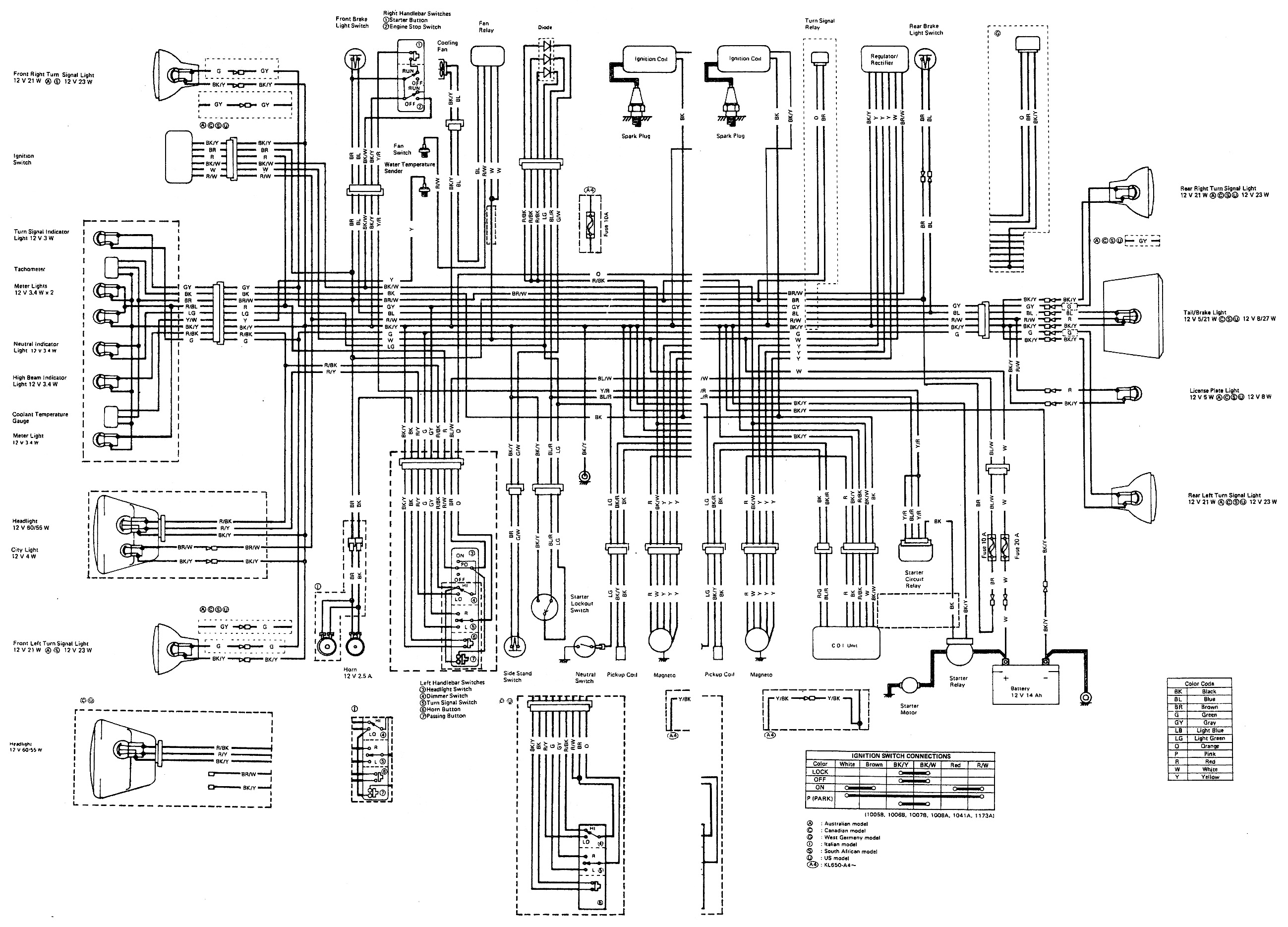
If you don't have a wiring diagram, download a copy from Mark's site. Wiring Diagram. If you print the diagram (maybe blow up the section you need), you will be able to use a marker to trace over the wires as you check to avoid being confused. Prepare to be annoyed, frustrated and confused but not necessarily in that order. Electrical is the weakest area in most technicians practice but shouldn't be because it is simply a matter of deduction (or maybe that should be induction! VBG) Time, experience and practice will see your skills improve. There is nothing magic about wiring! The relay circuit has two main parts, the part that controls the relay and the part that is controlled by the relay. A relay is simply a switch that is operated electrically. Allowing power to flow to the electro-magnet winding will create a magnetic field that attracts the contact arm. This is the "click" you hear when a relay operates- the relay contacts snapping together. When operating a switch, you perform the action that is done by the control circuit in a relay. A typical Bosch type relay has 5 connections as follows: 1 & 2- Winding (control circuit) has two connections, one for each "end" of the winding. 3- Contact arm (common in the switched or controlled circuit.) 4- Normally open contact. 5- Normally closed contact. Some relays share two connections to one connector as in a ground for the control winding connected along with the normally closed contact. The relay's controlled or switched circuit has the movable contact arm that is held away from the normally open contact by spring pressure. This "normally open" contact is simply that, normally open, not connected. When the relay has power applied to the magnet, "click" the contact arm's contact snaps against the normally open contact and power can flow through the circuit just like would happen if you touched two wires together or flipped a switch. Many relays have a normally closed contact also as I said earlier and the contact arm is in contact with the normally closed contact unless power is applied to the relay's winding. This normally closed circuit is useful to have something turned on when power isn't flowing in a circuit such as operating low beams then using a switch to close the relay to operate high beam. If the switch fails the circuit will fail with the low beams on so some lights will be always available. Consulting the wiring diagram will allow you to determine the wires that form the control and controlled (switched) circuits to the relay. Once you know which wire is which, you can use a test light or voltmeter to see whether power is available to the switched circuit (relay connector with one lead of your test light and ground with the other). You can easily make a test light for doing this with a small light bulb and socket. A pair of spade lug connectors on the ends of the bulb socket wires will allow you to plug into the relay plug connections for hands free. You should have power to one of the control circuit connections (per the wiring diagram) and the other connection should be connected to the bike's frame (ground circuit) when the radiator is hot enough to close the temperature switch. The ground circuit connects back to the battery negative to complete the path for power to the battery. My bet is that you have either, a broken wire making and breaking connection inside the insulation or a loose ground connection. To test for power to the control circuit connection on the relay connector, remember that this circuit is hot all the time so you shouldn't have to have the key on. In order to check the ground connection on the relay plug, you will have to remove the plug from the temperature switch in the bottom of the radiator and connect the wire to a good ground ( a bare metal part such as a bolt). If you plug a test light into the two control circuit connections in the relay plug, the light should come on whenever the temperature switch wire is touched to ground and go off when the switch wire is removed from ground. To test the controlled (switched) half of the circuit, the first test might be to connect a wire between the two connections for this circuit on the relay plug (per the wiring diagram). The fan should operate whenever these two connectors are bridged with a wire. If the fan operates with the controlled (switched) connectors bridged, wiggle, prod and push all the wires you can reach to see if the fan operates or stops (depending). If it does you will have to fiddle with the wiring to try to localize the intermittent connection. If it doesn't operate, try wiggling the wires to see if it operates as you will be trying to make the bad connection open and close the circuit in order to figure out where the problem lies in the harness. If this does not show up the fault, try the same thing by connecting your test light across the control circuit connections in the relay plug, then push prod and wiggle. Another option, if you can't locate the broken wire or bad connection is to determine whether the power wire or fan wire (load wire) is the one that is at fault. This will be useful if the wires are run together where the fault lies since wiggling the wires will not allow you to blame one wire in particular. In order to see which wire is at fault, first connect your test light from the powered connector (the one which comes from the battery positive through the fuse), to a good ground and do the wiggle bit. If the light will come on or off then this wire is at fault (or you haven't succeeded in operating the bad connection). If this doesn't show the fault, connect your test light from the battery positive to the switched contact of the relay connector plug (the one to the fan). The fan will not run because the test light has too much resistance to allow enough current flow to run the fan. On the other hand, the fan will allow ample current flow for the test light to operate so it should light. Now wiggle the wires to see if the test light flickers, goes off or comes on to locate the fault. Similarly, if the fault could not be localized to one wire in particular on the control side of the circuit, you can test the wires individually by connecting your test light from the battery positive to the relay plug connection which goes to the temperature switch, ground the switch connector and proceed to wiggle, prod and push. The other wire can be tested by connecting your test light between the control circuit's powered wire and ground, wiggle. If you can't locate the fault by this method then you may wish to simply rewire the fan circuit. Norm |