Home |
Community |
Forms |
Pictures |
Procedures |
- - - - - - -
- |
- - - - - - -
- |
| Mark's KLR650 Site Has Moved! *** This is old and outdated Information *** Please click the following link and change your bookmark to: ---------------------------------
|
MISCELLANEOUS
INFORMATION |
This
is the home of all the stuff that didn't really have a home. I
believe at least some of this will prove useful... |
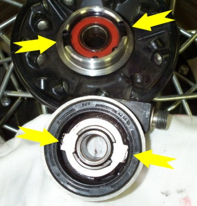 |
The
above picture shows the inside of the speedometer hub, (located
normally on the right side of the front wheel.) The yellow arrows
point to the tab ears, and the slots into which they fit. |
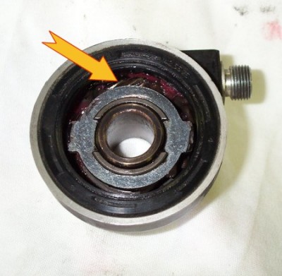 |
The
picture above shows the worm gear that requires a little grease.
Don't overgrease, and don't use anything too heavy. I like Mobil
synthetic grease for pretty much everything, including this area. |
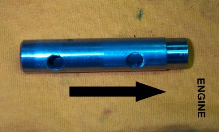 |
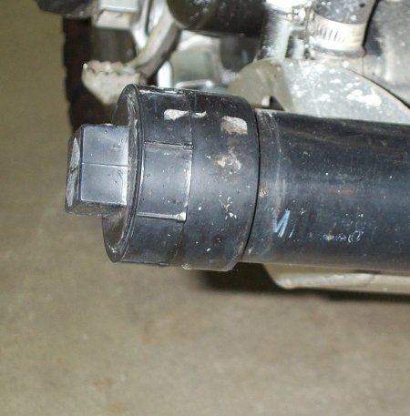
This
is the tube that runs from the oil filter cover to the engine.
It must be installed, and can only be correctly installed in this
direction - with the reduced end going in first. |
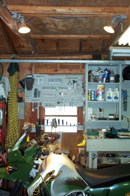 |
Good
lighting in a work area is obviously very important, and the addition
of spotlights makes valve adjustments so much easier by catching
the top of the bike in kind of a cross-fire. These are in addition
to the normal fluorescent lamps. |
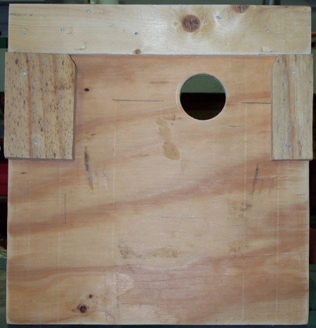 |
I found that with the bash plate off my bike, the lift brought the bike up securely but very unevenly. I had more things to do, such as a coolant flush, that required the bash plate to be off, so I made this temporary wooden "bash plate." This is just a square of 3/4" CDX. I put it on the two lift pads, and pumped it up to just touching the oil drain bolt. I circled the bolt head with a pencil, and cut out a larger circle around it for clearance. The strip of wood at the top of the picture brings the back end of the bike up and level. The two blocks on either edge are for easily positioning the bike. See the bottom picture in this set of three. |
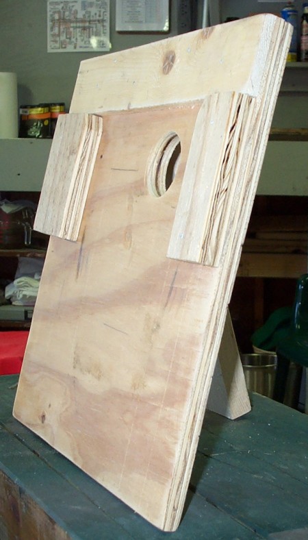 |
The long strip of wood at the top is a piece of 2x4, ripped to 5/16." This was the amount necessary to level the bike on the lift the way I wanted it. The positioning blocks are just scrap 3/4" plywood. With the bike on the board & up on the lift, I just laid the blocks in place, and marked a pencil line on the bottom for a perfect cut and fit. |
 |
The footrests don't need to be off for this. I had them off for photography during the doohickey upgrade, and just haven't put them back into place yet. Pump the board up close to the frame bottom, position the board/lift so that the footrest bracket is snugged up to the positioning block. This will give you consistent levelling of the bike when lifted. Then, just pump the lift! |
 |
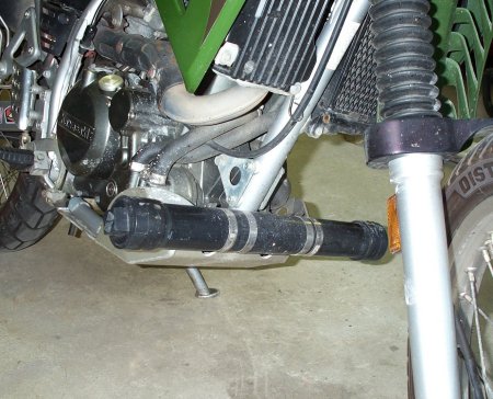
Here's a closeup of the ABS tool tube end. I used ABS only because I thought the black color would blend in better with the rest of the bike. I chose 2" (ID) ABS because I didn't need to carry a lot of stuff; I currently just have tire irons, hacksaw blades and a flare. This tool tube also serves as an excellent footrest, giving you a change of seating position on long trips. The total length of the tube, from end to end, is about 20". I chose this length because that's just inside the measurement from footpeg tip to footpeg tip. Just the tube itself is probably about 18.5" I got everything at Home Depot; 4 stainless hose clamps to keep it securely in place, a length of 2" ABS pipe, (I think it came in 10' lengths), the two adapters, the two end caps, and small containers of the special ABS cleaner and glue. The adapter is half smooth where it seals / welds to the pipe, and is threaded on the other half for the caps, or plugs. As you can see from the picture, I used recessed plugs with a large square center which can easily be turned by hand, the pliers of a multi-purpose tool, or whatever. It's very secure, but I don't know how it would hold up in a crash. I would hope that it would provide at least some kind of protection in the event of a tip over, but that hasn't been tested... |
 |
Here's
the full tube mounted. In addition to storage, it does work great
as a footrest. You can probably use larger pipe if you want to
carry more stuff, the 2" did all *I* needed it to. |
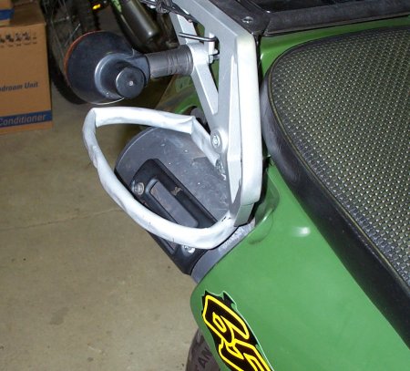 |
Thanks to Jonathan, I now have a set of Kawasaki saddle bags for my longer trips. Although I know there may be some scuffing of the side covers, I wasn't worried $180.00 worth about it - which is the pretty much the best price I could find for manufactured side racks. The picture above shows the "rack" that I made to keep the right bag off the muffler. I beat a piece of 1/4" EMT into submission, and then buffed it with a wire brush on a hand grinder. I removed the single bolt holding the muffler, marked the hole location from the backside with a Sharpie, and drilled the hole. When the Rustoleum paint had dried for a couple days, I installed the "rack" with a longer grade 8 bolt through the muffler-holding bracket using blue loctite and double nuts. |
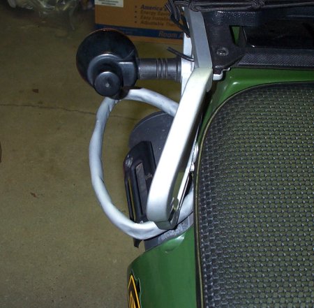 |
The
above picture shows Frankenstein's monster from the top. (Grin) |
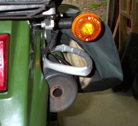 |
Last
but not least, the picture above shows that the EMT rack is doing
a good job of keeping the saddlebag away from the muffler. |
Here's an alternative from John: I cut a piece of diamond plate aluminum about the same width and ~ 3 inches longer than the existing heat shield. Removed the existing heat shield bolts, and bought ~2" replacements and a large stack of washers. Put the factory shield back in place, then my diamond plate shield, held ~ 3/4" off of the existing shield by the washers, then the replacement bolts running through the diamond plate shield, the washers (used as stand-offs), the factory heat shield, and into the existing bolt holes. |
 |
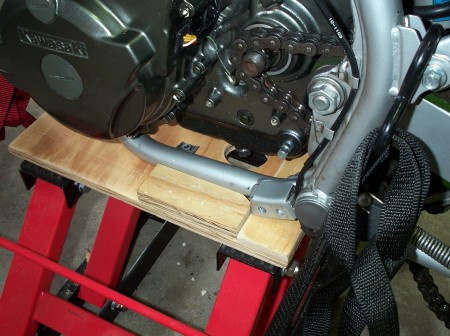
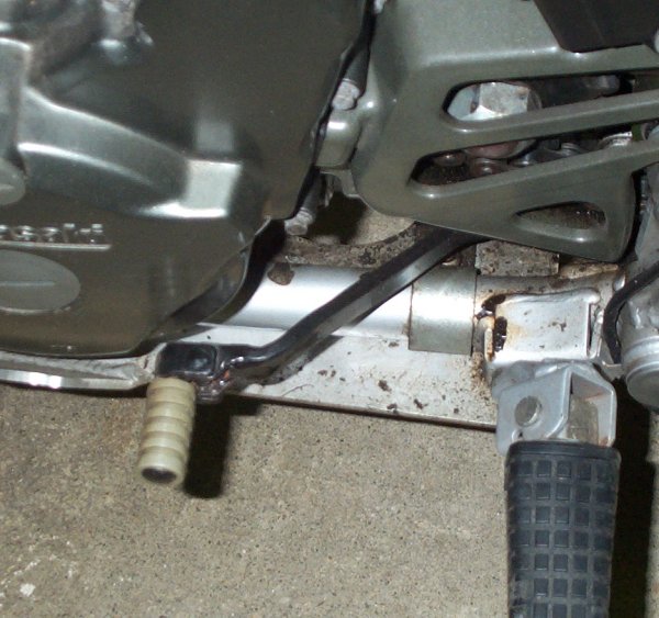
I
cut a notch out of my bash plate that allows me to easily remove
the protective rubber cap from the balancer adjuster bolt, and
use my socket on an extension to loosen & tighten the bolt
for adjustment. |
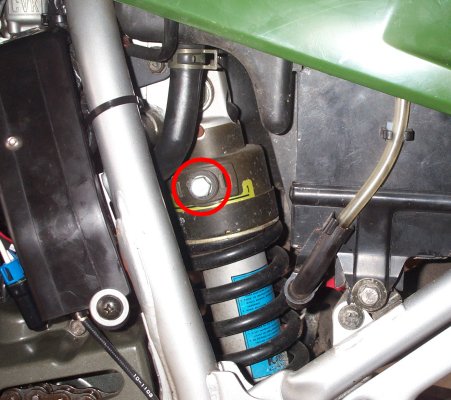 |
To adjust the shock spring preload, turn the adjuster nut, shown above circled in red: Turn counterclockwise to lower the number for a softer ride Turn clockwise to raise the number for a stiffer ride |
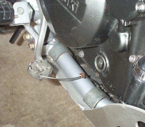 |
The
MSR Brake Saver is shown in the image above. I secured it around
the stock bash plate mount, and to the front of the brake pedal,
as shown. This will prevent brush, saplings and things like that
from sliding in there and breaking off the pedal. |
The
right rear wheel spacer is shown above. This must be replaced
when changing tires or whatever. |
The
left rear wheel spacer was a stinker to get a good picture of
because there's so little space between the swingarm and chain
/ sprocket. The spacer is indicated in the picture above by the
yellow box. You can see the shine of it about in the middle. |
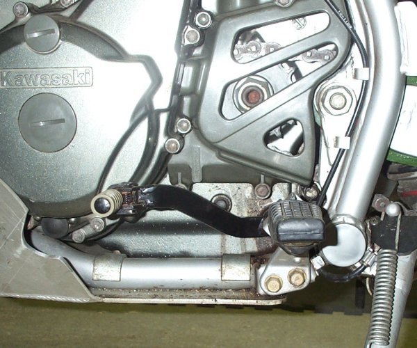 |
This is the IMS shifter mounted on my KLR.
(That's not a countershaft seal leak, just a heavy-handed application
of WD40) |
 |
Here
is a view of the IMS shifter from the top |
Doohickey
Removal & Installation Tools Info for the Do-It-Yourselfers |
 |
 |
 |