Home |
Community |
Forms |
Pictures |
Procedures |
- - - - - - -
- |
- - - - - - -
- |
| Mark's KLR650 Site Has Moved! *** This is old and outdated Information *** Please click the following link and change your bookmark to: ---------------------------------
|
REMOVAL &
INSTALLATION OF THE IDLER SHAFT LEVER - (DOOHICKEY) -
AND SPRING |
I followed the procedure written by the pioneer of doohickey replacement, Devon Jarvis. I don't claim to add anything new or improved to Devon's excellent work. The only reason for this procedure is to add some additional pictures and text which - hopefully - will help people with more modest mechanical skills to successfully take on this removal and replacement process.
|
Replacement Idler Shaft levers, springs,
associated parts and tools are available at: |
Dave "Jake"
Jakeman : Sagebrush
Machine Shop |
Fred Hink : Arrowhead
Motorsports |
For
the Do-It-Yourselfers... |
 |
 |
 |
|
If you find that either the doohickey or spring is bad in any way, you should report it. With enough complaints, Kawasaki will be forced to address this problem. Go to: http://www-odi.nhtsa.dot.gov/ivoq/ to report. |
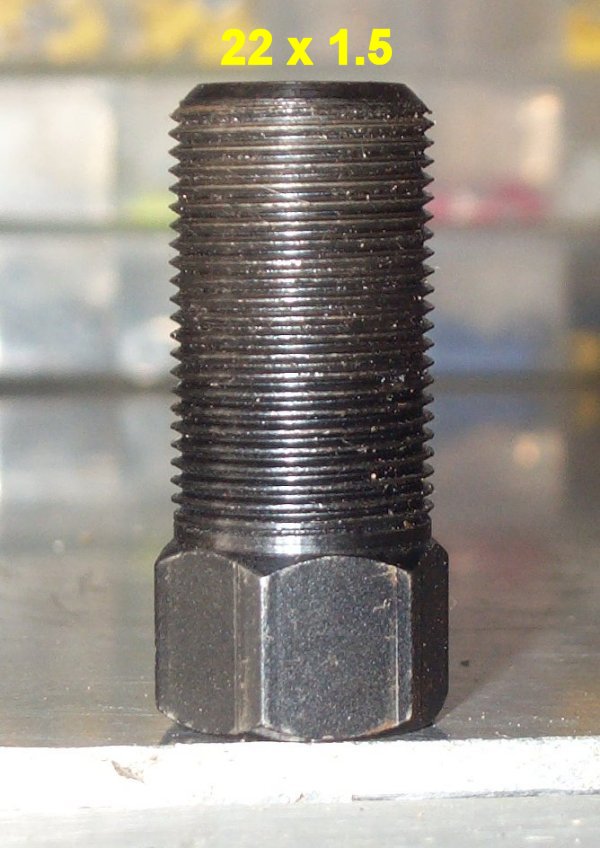
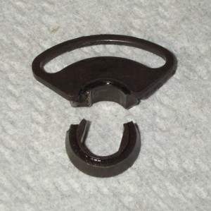
UPDATE! |
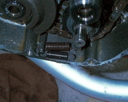
I recently checked over a friend's new-to-him
1999 KLR650, which had about 7200 miles on it at the time. The
spring was intact, but the "collar" of the idler shaft
lever (doohickey) was broken, as shown below. |
 |
 |
Be sure the
engine is clean, and free of mud or other junk that might fall
into the opened case. Good lighting, and a clean environment are
also good things. :) |
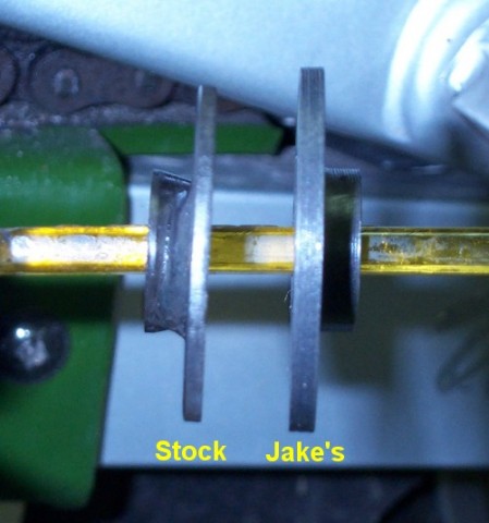 |
Above
is a comparison of the original stock (doohickey) idler shaft
lever, and the replacement one made by Jake. Clearly, Jake's is
MUCH beefier, - with no weld - and so elegantly
machined that I felt as though I should hang it over the mantle,
not put it into the oily engine. :) |
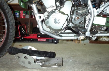 |
I chose to drain the oil, and do this procedure with the bike upright on my Easy-Lift in case any small parts fell off or out, they would just fall down, and not into the engine. As it turns out, I didn't really see anywhere the washers, locating "dowels" or woodruff key could fall into that wouldn't be easily accessed unless you're not going to remove the inner case cover for spring replacement. Then it might be a minor hassle to drop something. So, lean the bike over onto a bucket or a couple tires and don't drain the oil, or do as I have and drain the oil if the bike is due for a change anyway. As shown above, remove the bash plate, if you have one installed. I don't remember or know if the stock plastic one would interfere with bolt and cover removal or not... |
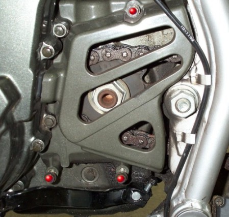 |
The
picture above shows the 3 bolts to remove sprocket cover, marked
here with RED
dots. |
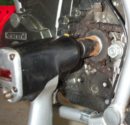 |
NOTE: I have a 16t sprocket, which lives very close to the wiring. I was afraid of an unfortunate wiring snag on the sprocket while pulling the cover away to break the magnetic attraction, and removing the sprocket eliminates the possibility of that snag. I also planned on removing the swingarm and chain for maintenance, and removing the sprocket makes all of that easier. It's not necessary to remove the sprocket to do this procedure. If you do remove it; righty-tighty, lefty-loosey. Shown above is the removal of the front sprocket. You'll need to loosen the adjusting nuts on both swingarm ends, and the axle nut. Push the wheel forward as much as possible, and roll the chain off the rear sprocket. This is another reason I chose to use the Easy-Lift. To avoid re-adjusting your chain, it may be possible to loosen the axle nut, and remove the axle. Slide the wheel forward until you can take the chain off the rear sprocket. Then, remove the wheel. A 27mm socket removes the stock nut, or a 30mm if you're using Jake's replacement. (Which I bought, and immediately lost somewhere.) Remove the sprocket, and the chain should position itself around the countershaft. For reinstallation
of the nut, the torque values are: 98 N-m (or)
10 Kg-m (or) |
 |
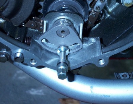
(Footrest removed for the photo.) It took me a couple tries to find the perfect shifter postition when I replaced the stock one with this IMS shifter from Arrowhead. To avoid the hassle, I'd suggest you engrave or scribe a mark on the shifter / shaft end, as shown above, so you can easily put the shifter back on exactly as it was. |
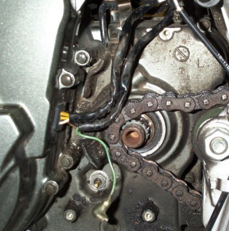 |
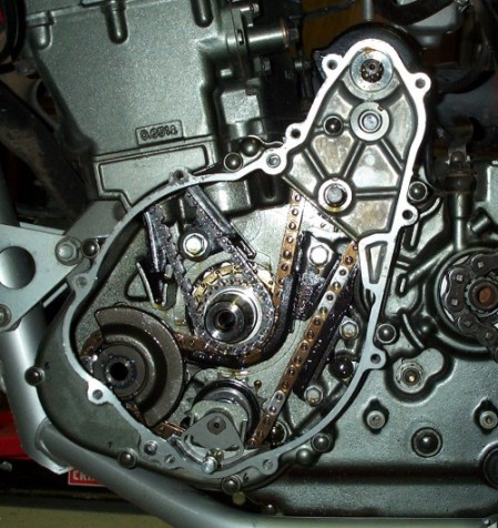
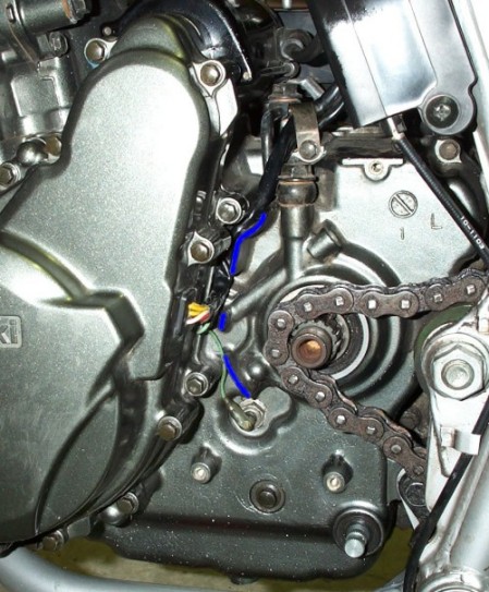
You'll see some of the pictures show everything all gunked up, as in the one above, and others where the case is clean. I took a couple minutes with a rag dipped in gas to wipe off the results of overspraying the chain. More is better, right?! (Grin) As shown in the picture above, remove the wires from the barriers in which they live, and unplug the single green neutral wire. You'll probably also want to take the wires out of the soft metal holder at the top of the engine to give them more freedom to move. |
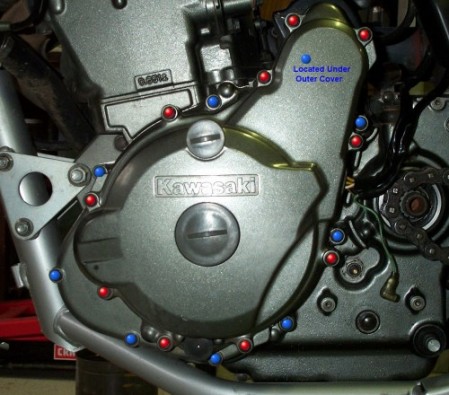 |
OK, here we go. The wires have been freed or unplugged, and the next step is to remove the outer cover. Picture above. The RED dots show the location of the bolts to be removed. There are 10 of them, and they are all the same size, so you don't have to worry about keeping them in order. (The BLUE dots are the inner cover bolts, to be removed if you're going to also change the spring. This is mentioned in more detail later on.) In an effort to preserve the gasket - which did come off in great shape - I unthreaded all the bolts almost all the way out. I worked the cover outward until, with a a fine-bladed screwdriver, I could work all the way around to free the gasket. It was stuck here and there, especially where the wiring enters the cover, and I'm sure this helped save it. Have some wire handy, and completely remove all the bolts. The cover is now ready to be taken off. There are tabs on the cover that can be used to get a grip on it. Use these to pull the cover straight back toward you. With the wiring free on the right side, the cover should come off with minimal effort. There is a magnetic attraction going on there, but nothing major. |
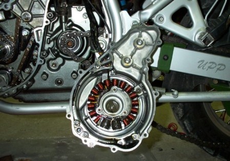 |
The picture above shows the cover wired to a frame tube, and safely out of the way. I left the gasket in place until I was ready to clean things up, and put the cover back on. My footrests were off for a better picture of the shifter scribe mark, and I needed more Loctite to put them back on. You can rest this cover on your footrest, but I still recommend wiring the cover to something to prevent it from falling during the body-building events. (Removal and installation of the rotor holding bolt.) |
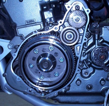 |
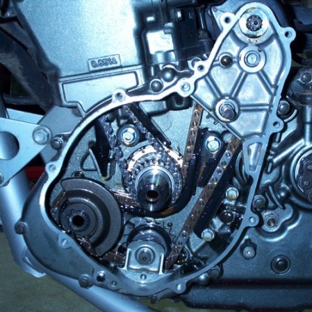
The
above picture is mostly for reference, a visual aid to show what
is where just under the left side cover. |
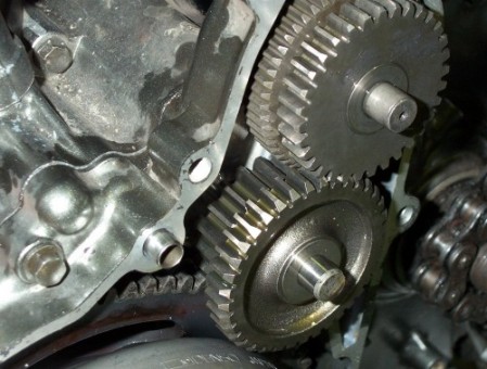 |
The next step is to remove these two gears. Each pair, top and bottom, has a thrust washer in front, and one behind. Make sure they all come off, and they all go back on! The picture above is a closeup to show the arrangement of the gears. Each pair has one gear larger than the other. The smaller one goes out at the top, and the smaller one goes in at the bottom. |
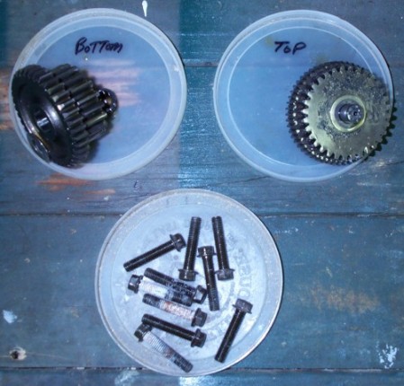 |
This is probably an unnecessary thing to do, but it saves from those brief flashes of panic when you're not sure what goes where. The picture above shows coffee can lids. I mark them with either what is in them, or where the parts came from. There's no question or hesitation when it comes time to reinstall, and the Sharpie marker washes right off with a little gas for the next use. |
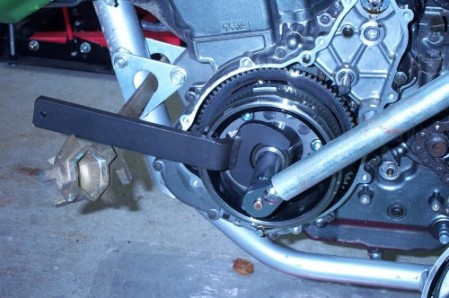 |
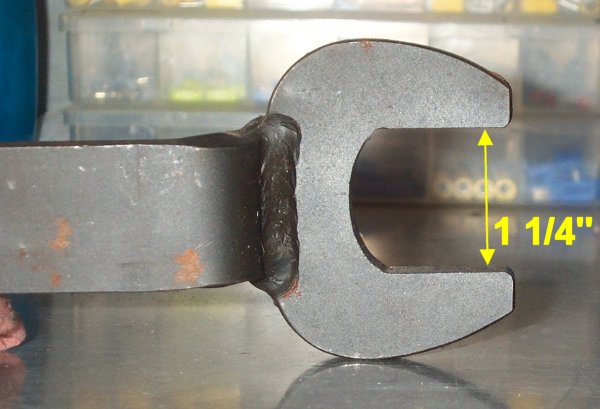
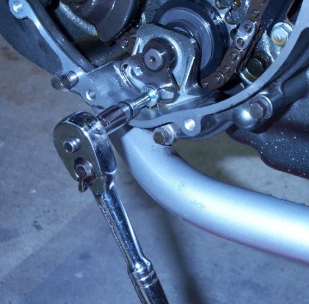
| OK, the thing is that the rotor holding bolt goes on with 130ft-lbs, so you will have to put some elbow grease into getting it out. You can use a honkin' big pipe over the wrench, as shown in the last picture in this procedure, or do something along the lines of what I did. (For the curious, that's a barrel cap tool that I'm using.) The wrench goes over the stop, footrest, highway pegs... whatever. REVISION! : For the second doohickey check & installation on my friend's bike, I used the footrest to hold the wrench in place. This worked MUCH better, and is the method I would highly recommend. The rotor holding bolt comes out counter-clockwise. I don't have a breaker bar, or whatever, so I just put a pipe over a ratchet. The rotor holding bolt is just that, unthread it all the way and put it aside. I recommend that you do NOT reuse it. For a savings of $12, why take the risk?! NOTE: I started out using a standard Craftsman deep well 19mm standard socket, and split it from stem to stern. I used a 19mm impact socket on my ratchet to finish the removal, and then to do the installation of the new bolt. I thought about using an impact wrench, but am not sure that it wouldn't cause damage in some way. |
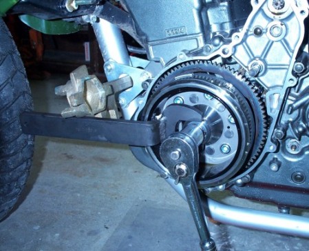 |
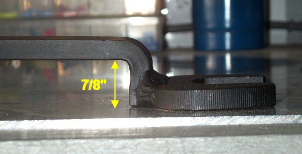
| The photo above shows the installation of the rotor puller, basically a big bolt. The torque required to pull the flywheel may be a little less if the bottom of the puller bolt has a dab of grease on it. I suspect that there may have been a lot of interference from the rather large bolt surface. Thread the puller into the hole that the rotor holding bolt used until you can't turn it by hand anymore. Now, set up the wrench slots as before, but this time, put the wrench under the stop. (See revision note below) You'll be turning in the rotor puller clockwise. I used a 7/8" impact socket on a ratchet. The socket was a perfect fit, which was good, because I don't have a metric one that would fit - I think it must be a 23mm...? REVISION! : For the second doohickey check & installation on my friend's bike, I used the footrest to hold the wrench in place. This worked MUCH better, and is the method I would highly recommend. The effort to thread in the puller and remove the rotor can be minimal, or quite a bit. I did my bike first, and it wasn't especially difficult to remove. I did the next bike, (the one that had a broken lever, pictures at the top of this page), and found that it just about required two men and a mule to get it loose. Once you can feel the rotor coming loose, just slowly turn in the puller until the rotor is freed. I think you might be able to pull it too far with the bolt, and have it fall off onto the floor. I wondered about that, stopped to check where things were, and was able to easily slide the rotor the rest of the way off the shaft by hand. The rotor was heavier than I had expected, so be aware of that to prevent dropping it. The force required to remove the rotor puller bolt from the threads was kind of surprising. I assumed it would just thread out by hand, but it did require more ratchet effort than you would probably expect. NOTE: The rotor has a magnetic attraction, and should be checked and cleaned of any metal chips and debris that may be living there. |
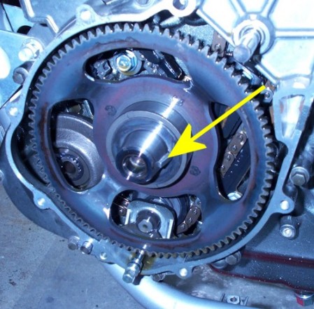 |
In the picture above, the arrow is pointing to the woodruff key. This is something you'll be needing again later on! The starter gear is loose, and spins easily. Just push it slightly back if necessary, remove the woodruff key from its slot, and then slide off the thrust washer. The starter gear will now easily come off the shaft. The woodruff key / flywheel re-installation goes much easier if you remember to rotate the shaft so that the keyway is facing up AFTER pulling the flywheel pops loose and BEFORE you actually pull the flywheel off - use the flywheel to have it pointing north. That way gravity won't interfere with reassembly. |
 |
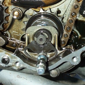
My
stock doohickey, shown above, was apparently still in good shape.
It had plenty of travel left, and there was no visible problems
with the weld. (See the update at the top of this page for one
with less mileage that wasn't ok.) There's only just over 8,000
miles on the bike, though, so I'm sure the low mileage is the
reason everything was still intact. Even if I had know this ahead
of time, I would still have replaced the doohickey and spring
for the peace-of-mind factor. |
 |
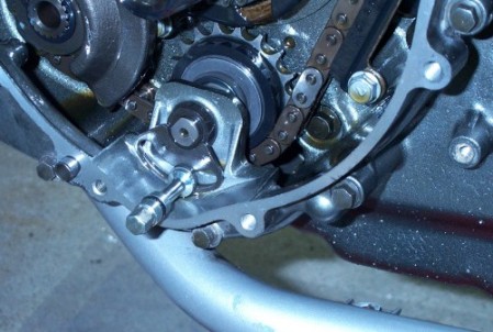
The
photo above shows the removal of the lever adjusting bolt. Counter-clockwise
to remove the bolt, and then just slide the doohickey off the
shaft. |
 |
Note that in the above picture the inner cover is still in place. The adjusting bolt and doohickey have been removed. The next thing to do is remove this inner cover in the same way as the outer cover, carefully to preserve the gasket. Again, unthread all the bolts almost all the way. Use the tabs to pull the cover out toward you until you can work a fine-bladed screwdriver all the way around to loosen and free the gasket. Then, with the gasket not stuck to either surface, remove all the bolts and the cover. Be aware that there are two locating "dowels" per cover, (inner and outer), and may stay in the engine case as mine did, or come loose with the cover. WARNING! Once the inner cover is off, and the lever spring is removed, it's possible for the adjuster shaft to slide out enough for the rear spacer washer to slip off, and bounce into the crankcase, or be lost in the work area. This is pretty much only an issue if the bike is on the sidestand. I did the first one with the bike upright on my Easy-Lift, and subsequent ones with the bikes leaned right over on a couple old tires, and had no problems. See below for a note on cover removal. |
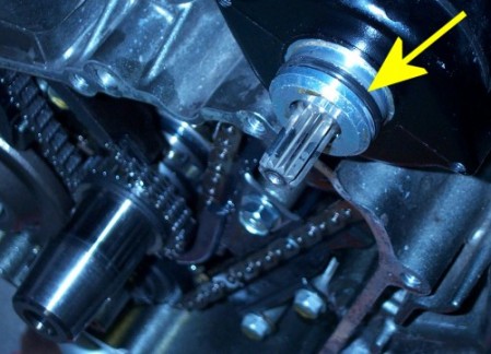 |
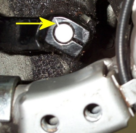
The
cover comes off without too much effort, but like the oil filter
cover, you'll be fighting a little with an O-ring. The yellow
arrow is pointing to it in the photo above, and is the obstacle
in the removal of this cover. |
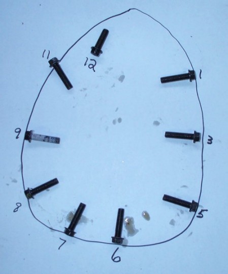 |
I
made a bolt chart for the inner cover because the first two bolts
I removed were of different lengths. (I labelled them according
to approximate clock positions.) As it turns out, #12 in the chart
- the bolt at the top inside of this inner cover
was the only short one, all the others were the same length. |
| NOTE:
It's recommended that you liberally coat the parts as you reassemble.
Be especially sure to reinstall the rotor and starter ring gear
wet with oil, or some other assembly lubricant such as molylube.
More is better, but make sure that the inside of the rotor and that tapered shaft are clean and dry. A small dab of grease in the slot where the woodruff key lives is fine, and will help keep the key in place during assembly. |
 |
The picture above shows the spring installed, with the stock one laying alongside. The spring has tension on it, but not much. Next time I open up the left side, which will probably be for no reason other than to replace the spring, I'll put in a shorter Eagle Mfg. spring from Arrowhead Motorsports. During the spring change I maintained some back pressure on the "tab" that the spring connects to. This is just another one of those anal retentive things, I guess, and probably isn't necessary. To remove the stock spring, slide the front (left in picture) end of the spring off the case post, and then just unhook the other end. To install the new upgrade spring, hook the back (right in picture) end of the spring into the hole of the tab, and then with needle nose pliers, or whatever works best for you, slip the other (left in picture) end over the case post. NOTE: I'm told that it isn't necessary to remove the cover to replace the spring. That you can just remove all the screws, wiggle the cover out a little, and work the spring in. To be honest, I fooled around with the spring before removing the cover, and couldn't get at the end behind the doohickey. |
 |
| The picture above shows the new doohickey and adjusting bolt installed. The adjuster bolt was threaded in just for the picture, and should probably not be there just yet because you may have to file the doohickey a little so that all 4 start gear spokes clear it. Notice the cover locating "dowel" in the bottom left of the picture, right next to the last bolt head that you can see. There are two per cover, (inner and outer), and may stay in the engine case as mine did, or come loose with the cover. |
 |
| Note that in the picture above the new doohickey and spring have been installed, and the inner cover is in place. Ignore the adjuster bolt in this picture, you don't want it installed just yet. I'm a big fan of the non-hardening (silicone) gasket stuff, such as YamaBond. You can use ANY non-hardening gasket agent material, or none at all, if that is your choice. If you do use it, I would suggest that it be used on both sides of the gasket to be sure of a good seal. Whether you choose to use something like this or not, the metal surfaces should be clean, dry and free of any stuck-on gasket material. You should also carefully wipe any junk or residue from the gasket itself. Note on the silicone: Use a small amount of non-drying silicone all around the rubber gasket surface of the valve cover. Be sure to wipe off any excess from the inside and outside edges of the cover. Again, you want very little here, just enough to lightly coat the surface and create a seal. I apply a small line of the silicone all the way around the gasket, then place my index finger on the top of the gasket, my thumb on one side of the gasket and my forefinger on the other side. I then just run around and around the entire gasket / cover surface until I have complete coverage of the gasket using the smallest possible amount of silicone. Be sure to get the silicone all around the two "circles" on the left side. Tighten the bolts in a criss-cross pattern, and don't fully torque each bolt all at once. Work your way around evenly several times until you've gotten the torque click, or reading, at each bolt. The cover bolts are torqued to 8.1n-m / 6 ft-lbs / 72in-lbs |
|
The picture above shows the starter gear again. You should not have the doohickey adjusting bolt installed yet. The first thing to do is slide the starter gear fully onto the shaft, and spin it slowly by hand to be sure all spokes clear the new doohickey. On mine, 3 of the spokes cleared easily, but the 4th was just kissing the top outer edge of the doohickey. A few passes with a file fixed this, and I was ready to continue the installation. Once you're sure all 4 spokes of the starter gear are going to clear the doohickey, you can remove it and install the adjusting bolt, tightening it to about 8.5ft-lbs or 104in-lbs. NOTE: The woodruff key / flywheel re-installation goes much easier if you remember to rotate the shaft so that the keyway is facing up AFTER pulling the flywheel pops loose and BEFORE you actually pull the flywheel off - use the flywheel to have it pointing north. That way gravity won't interfere with reassembly. Slide the starter gear fully back onto the shaft. Slide the thrust washer over the shaft and up to the starter gear. Next is the woodruff key and rotor. I had no trouble with this at all, although that seems to not always be the case. I placed the key in its slot, and got down so I could see directly into the slot of the rotor. As I pushed the rotor into place I just made sure that the woodruff key was travelling smoothly along the slot of the rotor. If you do have trouble with the key, you might try putting a dab of grease on it to hold it in place. This was not a a problem for me, (and probably won't be for you?), but if you have trouble making the one-way clutch of the rotor move onto the bushing correctly, try rotating the starter gear as you kind of rock the rotor into place. |
|
Above is the same photo used earlier during the removal steps, but it's just as relevant here. I suggest you use a new rotor holding bolt, which you can get from Fred at Arrowhead Motorsports, or wherever. The jury is still out on whether you can safely reuse the bolt or not, and I know that some people have reused them a couple times. In my humble opinion, it doesn't make sense to buy a new doohickey and probably the tools to install it, take the time to install it and then try to save $12 dollars by not also buying a new bolt. Whatever you decide, installing the rotor holding bolt is next. Place the wrench under the stop - you're going to turn clockwise here. NOTE: - Tighten the magneto flywheel bolt (rotor bolt) to 120N-m / 12.0kg-m / 87ft-lb's. Do not overtighten it now. - Loosen the bolt and then tighten it again to the same torque: 120N-m / 12.0kg-m / 87ft-lb's. - Finally, tighten the bolt to the specified torque: 175N-m / 18.0kg-m / 130ft-lbs |
|
Next is to install the starter gears. Make sure there is one thrust washer behind each gear pair, and one in front of each pair! Try starting the two pairs on together, and then pretty much let them do their own thing to find their way home. For the second installation, I did them individually and found they went on with little trouble. Rotating the starter gear slightly will probably make the installation easier. |
| The outer cover is just a repeat of the inner cover. Make sure the locating dowels are in place, (2), and that you've cleaned and prepared the gasket and mating surfaces. Apply the silicone gasket agent, if you choose. And again: I'm a big fan of the non-hardening (silicone) gasket stuff, such as YamaBond, and used it on the two cover gaskets to be sure of a good seal. Whether you choose to use something like this or not, the metal surfaces should be clean, dry and free of any stuck-on gasket material. You should also carefully wipe any junk or residue from the gasket itself. Tighten the bolts in a criss-cross pattern, and don't fully torque each bolt all at once. Work your way around evenly several times until you've gotten the torque click, or reading, at each bolt. The cover bolts are torqued to 8.1n-m / 6 ft-lbs / 72in-lbs |
 |
With the cover back in place, make sure to carefully put the wires back behind the protective barriers, outlined in BLUE in the above picture. I put a dab of di-electric grease in the neutral switch connector before pushing it back over the connector stub. With the chain already off at the front, you're a couple steps ahead of the game concerning other maintenance such as the swingarm lube, and chain cleaning and adjustment. No time like the present! |
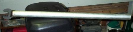 |
I
had a piece of large conduit that fit perfectly over the end of
the wrench. This is another alternative to the bar through the
engine support brackets. You'll need something
like this to achieve the amount of necessary force if you don't
use the footrest, highway pegs, or whatever. |